Simple remote tuning for the VFO
An easily-made unit with minimum drift.
In the August issue of QST, W3ASW pointed out the possibilities that the Clapp VFO circuit offered in the way of remote tuning and the advantages to be gained by such a system. This article describes the practical construction of a unit incorporating the principles set forth in that article. It not only affords a simple means of feeding a VFO to an existing transmitter but also results in reduced frequency drift.
As pointed out previously, the series-tuned Colpitts (Clapp) VFO circuit lends itself especially well to remote tuning control.(1) This refers to the currently popular scheme in which the VFO is placed on the operating table where it can be tuned conveniently, while the rest of the rig may be several feet away. Such an arrangement often involves complications, such as the need for an additional tuned circuit at the output end of the cable coupling the VFO to the transmitter. This is particularly inconvenient if the transmitter stage being fed is normally a crystal oscillator.
The Clapp circuit has the advantage that the tuned circuit can be separated from the VFO tube through a cable several feet long not only with negligible loss, but also without reaction on the frequency by movement of the cable. However, perhaps the greatest advantage in this arrangement is that separation of the tube and tuned circuit reduces temperature effects (drift) to a minimum. It also permits mounting the coil in its enclosure without regard to other components. The coil can be placed at the center of the box with maximum spacing from the sides and, as a consequence, minimum sacrifice in Q.
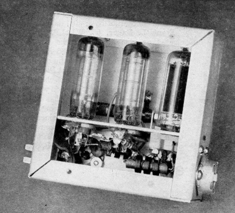
In this instance, the VFO consists of the two shielded units shown in the photographs, one containing the tuned circuit (Fig. 1B) and the other the 5763 oscillator tube and a pair of 0B2 voltage regulators (Fig. 1A), because the VFO was designed primarily as a driver for the "Band-Box" frequency multiplier described in the April, 1952, issue of QST.(2) However, in many cases, the crystal-oscillator tube of a rig can be substituted for the second unit mentioned, if the tube is a 6AG7 or 5763. If the popular grid-plate crystal-oscillator circuit is in use, it should be possible to feed the tuned circuit directly through the 2-conductor cable to the crystal terminals without modifying the crystal circuit in any way. The cable may be of any length up to 10 feet or so. RG-22/U is recommended.
The oscillator operates in the 3.5 Mc. region and the bandspread tuning system, consisting of C1, C2 and C3, is designed to cover the desired frequency ranges in three steps, when C1 and C2 are altered as described under Fig. 1. With one setting of C2, the tuning condenser, C1, spreads the range of 3500 to 3750 kc. out over 95 per cent of the National ACN dial. Since this fundamental range covers the most-used 80-meter c.w. frequencies, and harmonics of this range cover all of the higher-frequency bands, excepting only the 11 meter band, this range will usually suffice for 90 per cent of all operating. By shifting C2, the range of 3750 to 4000 kc. is spread out over about 75 per cent of the dial. The 27 -Mc. band is provided for by a third setting of C2.
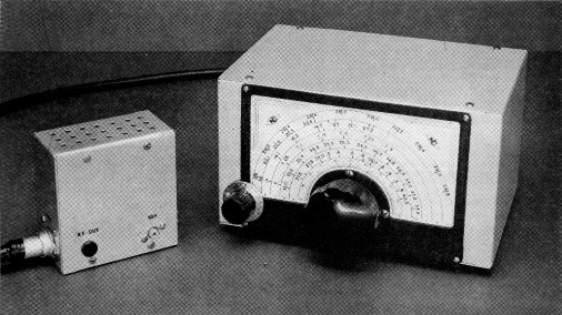
The remotely-tuned VFO. The large box contains the tuned circuit, the smaller one the oscillator and voltage. regulator tubes. The two terminals on the smaller box are for output and key connections. The power connector is at the end opposite the cable connection.
Construction
The tuned circuit is housed in a 5 × 6 × 9 inch aluminum box. An enclosure of this size is needed not only to provide mounting for an adequate dial, but also to permit spacing the coil well away from the sides of the box so that its Q will not be drastically reduced by the shielding in its field. Incidentally, tests showed that although larger coils had a higher Q before they were placed in a box of this size, the Q of the B&W "J" coil was only negligibly less when the coil was enclosed. Some increase in Q can be obtained by using a larger coil, such as the "T" series B&W unit, provided that a much larger enclosure is used.
The dial is first mounted centrally on one of the 5 × 9 inch sides of the box. The tuning condenser, C1, is then coupled to the dial and the mounting step at the rear of the condenser is supported against the bottom of the box with a heavy metal spacer cut to fit. The bandset condenser, C2, is shaft-hole mounted 1 inch in from the left side and bottom of the box. This necessitates drilling the shaft hole through the edge of the dial frame. C3 is soldered directly across the terminals of C2. The knob is a National HRS-5.
The B&W coil is removed from its mounting by first drilling out the rivets in the plug-in base, leaving the metal angle pieces at each end attached to the coil, and unsoldering the leads from the pins. The link winding is carefully removed by snipping the turns and prying the spacing blocks loose with a knife. One turn is removed from the coil itself. The coil is then mounted on National GS-1 pillar insulators so that it will be centrally located in the box in both directions.
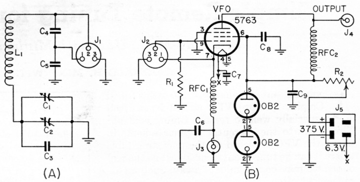
Fig. 1. Circuit of the remotely-tuned VFO.
| C1 | Approx. 12 pF variable (Hammarlund HF-15, rear stator plate removed, rear rotor plate bent; see text). |
| C2 | Approx. 23 pF variable (Hammarlund 11F-35, last stator and last two rotor plates removed). |
| C3 | 39 pF silvered mica. |
| C4,C5 | 1 nF silvered mica. |
| C6,C7,C8,C9 | 1 nF disk ceramic. |
| R1 | 47 kΩ, ½ watt. |
| R2 | 10 kΩ, 10 watt, with slider. |
| L1 | 35 µH - 39 turns No. 18, 1_7/8 inch long, 1½ inch diam. (B&W JEL-80, 1 turn and link removed). |
| J1,J2 | 3 contact female jack (78-PCG3F). |
| J3 | Key jack phono input jack. |
| J4 | Insulated phone-tip jack. |
| J5 | 4 contact male connector (C-J P-304-AB). |
| RFC1,RFC2 | 1 mH r.f. choke (National R-50). |
NOTE: RG-22/11 remote cable is terminated at each end with Amphenol 91-MPM3L male connector to fit J1 and J2.
The three-contact jack for the remote-tuning cable is set in the back of the box, and C4 and C5 are soldered to its terminals.
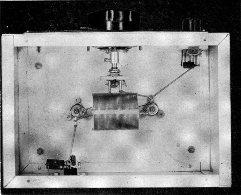
Interior of the tuned-circuit box. C4 and C5 are to the rear. C3 is soldered across C2 to the left in front.
The photographs show the essential details of the assembly of the tube unit. The enclosure is a standard 2 × 2 × 4 inch aluminum box. The three tubes are mounted on a shelf spaced 1M inches from the top of the box. This dimension is critical if the tubes are to be removed without difficulty. The keying and output jacks are mounted in one of the covers, below the shelf level, and the power connector is mounted at one end and the jack for the coax cable at the other. The resistor, R2, is mounted on top of the shelf, alongside the tubes, on the same side of the box as the keying and output jacks. This makes it possible to remove the tubes and adjust the slider by removing the blank cover of the box. The resistor is supported between two small angle pieces joined with a piece of threaded rod (or a long 6-32 screw) through the resistor form.
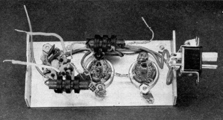
Bottom view of the tube-unit shelf. RFC1 is above, RFC2 below. C6 is soldered to J3 on the cover plate. The two leads going to the left solder to the cable connector. The one to the left above goes to J4, the lead to the right to J3.
All wiring, with the exception of the connections to the keying and output jacks and the cable connector, can be done before the shelf is placed in the box. This includes connections to the power connector which mounts from the inside. Leads of proper length are made for the jacks and cable connector, and these connections can be made after the shelf has been put in place, and just before the cover is put on. Care should be used in placing the tubes in their sockets, since there is little height to spare. If necessary, the tips of the tubes can be run up through the ventilating holes in the top of the box to allow the pins to clear the sockets.
Adjustment
Any power supply delivering between 250 and 400 volts at 50 mA or more may be used to operate this VFO. If a 120 mA transformer, instead of the 70 mA unit specified for the "Band-Box" in April QST is provided, the VFO and the multiplier unit may be operated from the single supply.
Adjustment of the frequency range for maximum bandspread is quite simple. Set C1 to a dial reading of 5. Then adjust C2 until the oscillator signal is heard on the receiver at 3500 kc. Set the receiver to 3750 kc. and adjust C1 until the signal is heard. If this occurs with the dial set at less than 100, carefully bend the rearmost rotor plate of C1 away from the adjacent stator plate, making sure that the plates do not touch and short the condenser in any position of the rotor. Turn C1 again to a dial reading of 5, reset C2 for 3500 kc., and check again for the point where C1 tunes to 3750 kc. By proper adjustment of the rotor plate on C1, the 3500-to-3750 kc. range can be made to cover the entire dial, or as much of it as desired.
After this initial range has been set, tune the receiver to 3875 kc. Set C1 to midscale and adjust C2 until the VFO signal is heard. Then the range of 3750 to 4000 kc. should be approximately centered on the dial with a coverage of about 75 divisions. The range can be shifted one way or the other by simply shifting C2 slightly.
If it is desired to center the 11-metet band on the dial, set C1 to midscale, set the receiver to 3387 kc. and adjust C2 until the VFO is heard. All three settings of C2 should be plainly marked so that they can be returned to when desired.
The cathode current (measured in series with the key) may vary over the tuning range from about 28 mA with both C1 and C2 set at maximum capacitance to 37 mA with both at minimum.
In using the VFO, the tube unit should be placed close to the stage to be driven and fastened securely to the chassis. A short lead should be used to connect the output terminal to the grid of the stage to be driven. If the driven stage has no grid condenser, a 100-ptfd. mica condenser should be connected between the output terminal and the grid of the driven stage. If more than adequate drive is obtained, the screen of the oscillator tube can be connected to the junction between the two VR tubes, rather than to the end of R2 (Fig. 1). This unit is not a power device, and adequate gain in the way of a crystal-oscillator tube or other buffer amplifier should be provided.
Notes
- Long, "Cutting down VFO drift," QST, August, 1952, p. 20.
- Mix, "The 'Bandbox' - a single control frequency-multiplier unit," QST, April, 1952, p. 11
Donald H. Mix, W1TS.