An inexpensive radioteletype converter
Simple unit for transmitting and receiving.
As those who operate radioteletype know, a device is required to change the audio tones at the output of the receiver to d.c. pulses that operate the printer and, conversely, to convert the d.c. pulses from the transmitting keyboard to audio tones for modulating the transmitting carrier. This article describes a simplified unit for this purpose.
The teletypewriter is a machine that can convert an appropriate series of pulses of direct current into a typed message at various speeds, usually up to a maximum of 60 w.p.m. This is accomplished by making use of a fiveunit-code pulse system in which various combinations of marking and spacing impulses operate electromagnets which set up code bars in the printer and mechanically convert the pulses into the correct information or functions. In addition to the five code pulses, a starting pulse and a stopping pulse are required. The time interval between the beginning of the starting pulse and ending of the stopping pulse is approximately 163 milliseconds.
The operation of these teleprinters on short telegraph lines using direct-current impulses requires the use of little external equipment other than a source of electrical power to operate the selector magnets and motors. In order to operate the printer with signals derived from a radio receiver tuned to a radio station sending printer signals, however, a separate piece of equipment is required. This unit is called a converter and is used to change or convert the radio signals into the proper sequences of impulses of marking and spacing currents required by the printer. In one system commonly used, the radio signals are received and changed to marking or spacing audio frequencies of 2125 and 2975 c.p.s., respectively. In the case of v.h.f. operation, these frequencies are the result of amplitude modulation of the transmitter carrier by means of an audio-frequency-shift keyed oscillator. The lower frequencies in the range below 30 Mc permit the use of carrier-frequency-shift circuits in the transmitter; in this case the receiver output is obtained by making use of the b.f.o. and beating against the carrier so that alternate audio outputs of 2125 and 2975 cycles are obtained.
The converter must have certain characteristics in addition to its function of changing the audio tones into marking and spacing current impulses. It must function properly even though the signals vary in amplitude or have poor signal-to-noise ratio. It must also produce direct-current signals which are free from bias or other forms of distortion. For optimum operation the d.c. impulses should exactly duplicate the original impulses generated at the transmitter end of the RTTY circuit.
The circuit
The circuit shown in Fig. 1 is a form of converter in which a few refinements have been eliminated to demonstrate the simplicity of equipment needed for radio use. This unit is, however, adequate for printing information transmitted by commercial frequency-shift stations operating in the h.f. bands at speeds of 60 w.p.m. The converter will operate with signals which are only 6 db. above the noise level. The equipment is specifically designed for use with a transmitter in the v.h.f. bands where amplitude modulation of the transmitter carrier is ordinarily employed; a circuit of a simple audio frequency-shift oscillator is included for use with the transmitter.
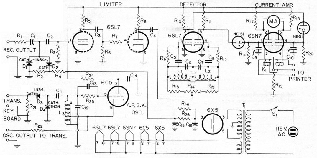
Fig. 1. Circuit of the radioteletype converter.
| C1 | 10 nF paper. |
| C2,C3 | 3 nF mica. |
| C4 | 50 nF paper. |
| C5,C8,C13 | 4,7 nF mica. |
| C6 | 150 nF paper. |
| C7,C14 | 100 nF paper. |
| C9,C10 | 1 nF mica. |
| C11 | 29 nF (approx.). |
| C12 | 30 nF paper. |
| C15,C16 | 10 µF 450 volt electrolytic. |
| R1,R2l | 33 kΩ, ½ watt. |
| R2 | 150 Ω, ½ watt. |
| R3,R7 | 470 kΩ, ½ watt. |
| R4 | 100 kΩ, 1 watt. |
| R5 | 220 kΩ, ½ watt. |
| R6,R9,R12,R13,R15,R22,R23 | 47 kΩ, ½ watt. |
| R8 | 100 kΩ, ½ watt. |
| R10,R11 | 2.2 MΩ, ½ watt. |
| R14 | 50 kΩ potentiometer. |
| R16,R20 | 1 MΩ, ½ watt. |
| R17,R18 | 270 Ω, ½ watt. |
| R19 | 1 kΩ, 1 watt. |
| R24 | 51 kΩ, 1 watt. |
| R25,R26 | 6,8 kΩ, 2 watt. |
| L1 | 36 mH (GE RLD-019 TV width control). |
| L2 | 29 mH (GE RLD-014 TV width control). |
| L3 | 95 mH (GE RLC-091 TV hor. oec. coil). |
| S1 | S.p.s.t. toggle. |
| T1 | Power transformer: 250-0-250 volt r.m.s., 30 mA; 6.3 volt, 3 A. |
A simple functional description of the operation of the various circuit elements follows: In receiving, the audio output from the receiver is fed to two germanium diodes, Dl and D2, that are biased with approximately 0.3 volts. The result is to limit the maximum peak voltage applied to the grid of the 6SL7 limiter tube to values of 0.14 to 0.6 volt with input-signal levels varying from 1 volt to more than 30 volts. The diodes are even more efective in clipping the peak amplitude of narrow noise pulses. The 6SL7 cascaded limiter-amplifier is used primarily to increase the level of the signal voltage, but a secondary function is to obtain additional output-level stabilization. The output signal amplitude is approximately 15 volts and varies ± 1.0 db. with input-voltage changes from 0.45 volts to more than 30 volt.
The output signals from the 6SL7 limiting amplifier are fed into the two parallel-tuned LC circuits, L1Ce and L2C7, which are resonant to 2125 and 2975 cycles, respectively. The potentiometer is used to adjust the ratio of the currents in the two windings of the polar relay, K1, when noise voltage only is applied to the converter input. The second 6SL7 tube is used as a grid-rectifying dual detector, and the plate currents of this tube will depend on the amount of signal applied to each grid. A marking signal present on the grid will result in the flow of grid current and will bias this grid to plate-current cut-off. The plate voltage rises from 15 volts to 50 volts and the series-connected neon lamp fires. This results in the application of about 25 volts of positive bias to one half of the 6SN7 polarrelay-keyer tube. This half of the tube draws 20 ma. of plate current and develops 20 volts of bias across the common 1000-ohm cathode resistor, R19. This voltage results in plate-current cut-off in the second half of the 6SN7 tube. A spacing frequency will cause the second half of the 6SL7 detector to function in the same manner and result in plate-current flow in the second half of the 6SN7 keyer tube.
The 6C5 tube is used in a Hartley oscillator circuit adjusted to oscillate at either the marking frequency of 2125 cycles or the spacing frequency of 2975 cycles, depending upon the action of the printer keyboard contacts. The output of this oscillator is used to drive the amplitude modulator of the transmitter. The power-supply requirements are very nominal and no explanation of the circuit is required.
Fig. 2 shows a plot of the polar-relay keying-tube plate currents, as indicated by the zero-center meter, as a function of the input frequency to the converter. The differential current falls to zero at the frequencies between 2400 and 2660 cycles because of the switching action of the series-connected neon lamps. The converter can be constructed without using neon lamps as switches; however an increase in the transition time between marking and spacing impulses may result.
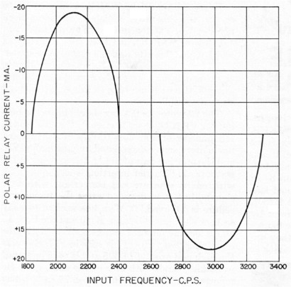
Fig. 2. Plot of relay current vs. input frequency.
Circuit adjustment
The adjustments required to put this equipment into operating condition are very few. The noise output of the radio receiver, with the antenna disconnected, is fed into the input of the converter and the potentiometer, R14, is adjusted until the meter is approximately centered on zero. When a marking signal of 2125 cycles is then applied to the input, the meter should deflect to the left and L1 should be adjusted for maximum deviation. With a spacing signal of 2975 cycles applied, the meter should deflect to the right and LQ should be adjusted for maximum reading of the meter in this direction. The deflections should be approximately equal for either a marking or spacing signal. If the readings differ by a large amount, it indicates that the 6SN7 tube may not have equal cathode-emission capabilities and should be replaced.
The a.f. oscillator can be adjusted to the correct frequencies by first adjusting the core in L3, with the keyboard contacts open. The core is adjusted to give 2975-cycle output from the oscillator circuit. The contacts are closed and C11 is adjusted until the frequency output from the oscillator is 2125 cycles. A recheck can be made of the spacing, and then the marking frequencies, and the adjustments retouched to eliminate the small errors caused by the slight interlocking of the adjustments. C11 should be varied in steps of approximately 500 to 1000 pF. The frequencies of 2975 and 2125 cycles are. nominal and may vary within ± 50 cycles without affecting operation. The a.f.s.k.-oscillator output can now be fed into the converter input, and the printer should be capable of a local operational test by printing correctly. If the machine runs open, the indication is that at some point in the circuit a crossover has occurred. A simple cure for this difficulty is a reversal of the connections to the windings of the polar relay.
Single-selector printers
This converter is designed for use with a Teletype Corporation Model 12 printer, with which an external power supply is required for the printer selector magnets. Anyone fortunate enough to have a Model 15, or any other printer which has a single selector magnet, can modify the converter described above so as to enable it to be used with these printers directly, thus eliminating the polar relay and the external power supply. This change is shown in Fig. 3. The 6SN7 polar-relay-keying tube is replaced by two tubes, each capable of passing 60 mA of cathode current. In this case the printer is connected in series with the marking-tube cathode circuit; the 60 mA of current, adjusted by R7, will directly operate the printer selector magnet.
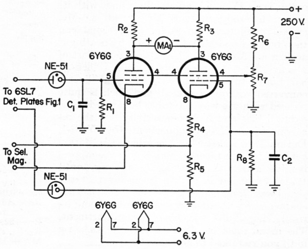
Fig. 3. Converter-circuit modifications for use with single-selector magnets.
| C1,C2 | 2 nF mica. |
| R1,R8 | 470 kΩ, ½ watt. |
| R2,R3 | 220 Ω, ½ watt. |
| R4 | 220 Ω, 1 watt. |
| R5 | 470 Ω, 2 watt. |
| R6 | 47 kΩ, 2 watt. |
| R7 | 50 kΩ potentiometer. |
Marvin Bernstein, W2PAT.