Measuring sideband suppression
Howard Wright, W1PNB, suggests the simple stunt shown in Fig. 1 for measuring sideband suppression of your own or the other fellow's signal. It requires that you have a selectable-sideband receiver of some kind (filter, YRS-1. etc.) and an oscilloscope, and the only other requirement is a calibrated volume control. The volume control is calibrated with an ohmmeter. Assuming a 1 megohm volume control, the -6 dB point will be at half resistance or 0.5 megohm. The -12 dB point will be at half of this, or 0.25 megohm. The -18 dB point is half of this (0.125 megohm), and so on down the line in 6 dB steps.
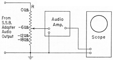
Fig. 1. By calibrating the volume control (R) of his selectable-sideband adapter, W1PNB gets direct readings of sideband attenuation.
The scope can be connected at any point in the audio amplifier following the calibrated volume control, and the sweep speed should be set low enough to make noise peaks appear as individual "spikes."
To measure sideband suppression, set the control at 0 dB and advance the r.f. gain control of the receiver to a point where the unwanted sideband gives a definite amount of scope deflection on peaks. Reduce the calibrated volume control setting (to save the loudspeaker) and switch to the desired sideband. Adjust the calibrated control until exactly the same amplitude peaks appear, and read the suppression ratio directly from the control.
The accuracy of the system is limited, of course, by the care taken in calibrating the control, errors in reading the scope, and by the maximum possible amount of sideband suppression the selectable-sideband receiver is capable of. However, the limit of the receiver rejection can readily be found by occasionally tuning across an unmodulated carrier and measuring the point of receiver failure. Any reports given below this ratio will be accurate.