Inexpensive L and C standards
One of the well-known uses of the grid-dip meter is as a calibrated source of r.f. in the resonant-circuit method of measuring inductance and capacitance. If the capacitance of a condenser is known accurately, the inductance of a coil connected to it can be determined from the frequency at which the combination resonates. Similarly, if a coil of known inductance is available the capacitance of a condenser connected to it can be measured. The accuracy of the method depends, among other things, on the accuracy with which the standard L and C values are known.
It is possible to get entirely adequate L and C standards for a matter of pennies, and the ingredients usually can be found in any radio parts store. Silver mica condensers are highly stable and their standard tolerance is plus or minus 5 per cent of the marked value. It is possible to get them with a tolerance of 2 per cent, but this usually will require a special order - which is slow going these days. Furthermore, it is not really necessary, since an inductance standard of the same order of accuracy is readily available in the B & W Miniductors. Being machine wound, these can be held to quite close tolerances in diameter and winding pitch, especially in sizes with the turns fairly well spaced. The 3015 type meets these requirements quite nicely.
By proper choice of values for the standards a range of L and C measurements that will take care of all the usual amateur requirements can be covered, without exceeding the frequency range commonly incorporated in a grid-dip meter. A good selection is 5 microhenrys for the coil and 100 Add. for the condenser. These will permit measurements of inductance from 0.1 to 100 µh. and capacitances from 5 /4.4f d. to 0.002 dd., with a grid-dip range of 1500 kc. to 50 Mc.
Seventeen turns of 3015 Miniductor (1-inch diameter, 16 turns per inch) has an inductance of almost exactly 5 microhenrys. To be usable, it has to be mounted in some way that will permit ready connection, and it is convenient to use a binding-post plate as shown in the photograph Ep. 120]. The 100-µµfd. silver mica can be similarly mounted, one plate of a pair being used for each unit. Ceramic plates are best from the standpoint of good electrical characteristics and mechanical stability, but the material is probably not too important. In cutting the coil to size, be careful not to distort the turns or disturb the spacing, and leave just enough lead length to solder into the lugs under the binding posts.
Fig. 1 can be used with a coil of this size and a run-of-mill 100 pF silver mica. Using this chart and the calibration of a commercial grid-dip meter, it was found that over most of the range the maximum discrepancy between values of L and C so measured and the values given by measurement on a Boonton Q-meter was under 6 per cent, and the average deviation was considerably less. The actual capacitance of the condenser assembly was 106 pF.
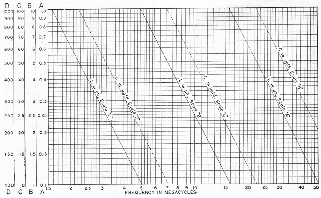
Fig. 1. Inductance and capacitance as a function of the resonant frequency of an LC circuit, based on an inductance of 5ph. for capacitance measurements and a capacitance of 100 pµfd. for inductance measurements.
Higher accuracy
Greater accuracy can be attained by making a few corrections. Since the coil is likely to be closer to exactly 5 µH than the condenser is to 100 pF, the coil can be used as a standard to determine the capacitance of the condenser. The inductance values given by the chart can then be corrected by the factor 100/C, where C is the actual measured capacitance including the mounting.
In measuring very low values of. L or C a correction should be made for the residual inductance and capacitance of the standards and their assemblies. The binding-post assembly alone has a capacitance of approximately 1 pF, which should be subtracted from the measured value of capacitance if it makes a significant change in the result. The residual inductance of the condenser assembly, as determined by shorting the binding posts (at the holes for the wire connections) with a large metal plate and measuring the resonant frequency, is approximately 0.02 µH, which similarly should be subtracted from a measured value of inductance if it changes the value materially. The lowest self-resonant frequency of the coil by itself is 150 Mc, sufficiently high as not to be important when the measuring frequency is below 50 Mc. When mounted to the binding post assembly the combination resonates at a little over 50 Mc.
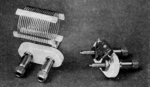
Low-cost standards of inductance and capacitance made from readily available parts. They will give sufficient accuracy, without special calibration, for most amateur purposes.
Probably the largest single factor in the overall accuracy is the accuracy with which the resonant frequency is measured. The cramped scale of the average grid-dip meter precludes reading the frequency very closely, and this, together with calibration errors, can cause an uncertainty in L and C values of as much as 10 per cent. This uncertainty can be greatly reduced by using the meter to get a dip -with the loosest possible coupling, of course - then leaving it set at the resonant frequency and picking up the signal in a receiver. The frequency can then be measured by any means the operator has available. For most purposes, however, it is hardly necessary to go to this trouble.