Combining the antenna coupler and low-pass filter
A matching unit for the 5763-6146 "75 watt" transmitter.
The unit described in this article was built as a companion to the transmitter described in December QST, carrying through to the antenna feeders from the output terminal of that outfit. It is complete with a low-pass filter for TVI reduction and includes an r.f. voltmeter circuit for checking power output, using the 0-1 ma. meter built into the transmitter. The same type of assembly can be used with other transmitters, up to 100 watts or better, that have been designed to put their power output into a flat coax line.
Althougth the antenna-coupling unit shown in the accompanying photographs was built as a matching unit for the 75-watt transmitter described in December QST,(1) the construction is suitable for any transmitter running 100 watts or so. It combines a number of things, such as a low-pass filter for TVI and an r.f. voltmeter circuit for checking power output, into one coordinated unit, in contrast to the more common practice of building such accessories separately. The voltmeter circuit is arranged to use the same 1-mil meter (with its 5000-ohm series resistor) that makes all the other measurements in the December transmitter.
The individual circuits are not novel; both the voltmeter circuit and the inexpensive low-pass filter have been discussed in previous QSTs, and the antenna-coupling circuit is the standard one modified to permit series and parallel tuning of the conventional type as well as matching the feeders to a coax link through the familiar parallel-tuned matching circuit. The arrangement is identical with one described in the 1953 Handbook. Two variable condensers are turned together through a right-angle drive, but their shafts are insulated from each other and from ground so they may be connected in various ways. For matching a parallel-conductor feeder to a coax link, this makes about as "universal" an arrangement as it seems possible to find; practically any random combination of antenna and feeder length can be matched to a 50- or 75-ohm line by using one coupling circuit or the other. It is equally possible to match a single-wire feeder or antenna working against ground, simply by grounding the center of the tank coil, L7 in Fig. 1, and treating the single wire as a one-sided feeder-system.
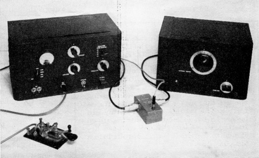
The combination universal antenna coupler, low-pass filter and r.f. voltmeter circuit is built in a small cabinet matching the 75 watt transmitter described in the December, 1952, issue. This illustration shows the set-up used for adjusting the coupler to match the impedance of the coax line connecting the two units. The s.w.r. bridge is a simple resistance type described in the Handbook.
Construction notes
The coupler is built on a 7 × 9-inch chassis and fits in an 8 × 12½ × 8½ inch cabinet (8 by 10 panel). The antenna condensers, C6 and C7, are mounted on triangular pieces of aluminum that in turn are supported from the chassis, at their corners, by 1-inch ceramic stand-offs. These assemblies are spaced so that there is room for insulated couplings between the condenser shafts and the right-angle drive unit, the shafts being cut off to suit. A little care should be used to line up the assemblies on the chassis so that the condensers can turn freely. The advantage of this mechanical arrangement is of course that the condenser capacitances are identical for a given dial setting, so that with the two rotors connected together the two operate together as a split-stator condenser. A regular balanced condenser could be used instead, but since such condensers have a shaft common to both sections the series-tuning connection cannot be used. As an alternative to the right-angle drive, a straight-through arrangement of two condensers mechanically connected through an insulated shaft coupling could be used, but there do not seem to be any condensers of the proper ratings available with tail-shaft extensions to make this possible.
For the parallel-tuned circuit the condenser rotors are connected together through a plug bar, made from aluminum, which fits into banana jacks mounted on the triangular plates. The jacks shown in the photograph are from jack-top binding posts, most of the post body being sawed off so the remainder could be used as a nut. We didn't happen to have any regular jacks at the time. When the bar is removed and the flexible leads from the output posts are connected to the condenser frames the circuit is series tuned.
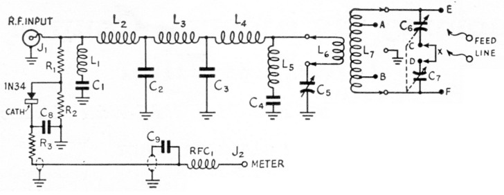
Fig. 1. Circuit diagram of the antenna coupler and low-pass filter.
| C1,C4 | 40 pF silver mica, 500 volt. |
| C2,C3 | 120 pF silver mica, 500 volt (50 and 70 pF units in parallel). |
| C5 | 300 pF variable, 0.024 inch spacing (Bud MC-1860). |
| C6,C7 | 300 pF variable, 0.026 inch spacing (National TMS-300). |
| C8 | 5 nF disk ceramic. |
| C9 | 1 nF disk ceramic. |
| R1 | 6.8 kΩ, 1 W composition. |
| R2 | 680 Ω, ½ W composition. |
| R3 | 1.5 kΩ, ½ W. |
| L1 | 6 turns No. 16, ½ inch i.d., 15/16 inch long. |
| L2,L4 | 9 turns No. 16, ½ inch i.d., 1 inch long. |
| L3 | 13 turns No. 16, ½ inch i.d., 1_7/8 inches long. |
| L6 | 3.5-7 Mc: 10 turns No. 16, 2 inches i.d., 10 turns per inch. 7-14 Mc: 6 turns No. 16, 2 inches i.d., 10 turns per inch. 14-28 Mc: 2 turns No. 16, 2 inches i.d.,10 turns per inch. |
| L7 | 3.5-7 Mc: 20 turns No. 12, 2½ inches i.d., 6 turns per inch. 7-14 Mc: 10 turns No. 12, 2½ inches i.d., 6 turns per inch. 14-28 Mc: 4 turns No. 12, 2½ inches i.d., 6 turns per inch. |
| J1 | Chassis-type coax connector. |
| J2 | Insulated tip jack. |
| RFC1 | 1 mH r.f. choke (inductance not critical). |
NOTE: Length dimensions of L1 to L3, inclusive, are measured between end turns and do not include lead lengths. Inductances should be adjusted as described in the text, if possible. L7 is B & W type 3905-1 coil material; L6 is B & W type 3907-1. L6 mounted inside L7 at center. L6-L7 assembly mounted on Millen type 40305 plug.
The coil socket (Millen 41305) is mounted on the same pillars that support the rear corners of the triangular plates, but there is no electrical connection between this socket and the plates. The center socket prong is grounded to the chassis directly underneath.
Low-pass filter construction
To simplify the mechanical work there is no shielding between the individual sections of the low-pags filter in this unit; instead, the coils are separated and so oriented as to reduce coupling between them. It is recommended that the layout shown be followed fairly closely for this reason. It is also advisable to separate the coax input terminal and the circuit formed by Le and C5 as much as possible. From an electrical standpoint the arrangement used leaves something to be desired, at least theoretically, but concessions have to be made to the physical characteristics of components and their relationship to an acceptable panel layout.
The dimensions of the filter coils are given in Fig. 1 and should be closely duplicated, especially if there is no calibrated grid-dip meter available for making adjustments as described earlier.3 The electrical constants of this filter are the same as those of filter B in the referenced article. The 1-inch ceramic pillars supporting the coils should be located as shown in the bottom view of the chassis. C1 and C4, the condensers in the series-resonant circuits, should be grounded as close as possible to the input and output terminals, respectively. In this unit, C1 is grounded at one of the screws holding the coax connector to the chassis, and C4 is grounded to a lug under the pillar supporting the junction of L4, L5 and the lead from Ls. The latter lead then drops through a hole in the chassis and connects to the coil socket on the other side.
Although the harmonic attenuation of the filter will not be affected to an observable extent by small deviations from the optimum constants, the impedance characteristics in the passband - especially near the cut-off frequency - will be better if the values are right. While departures even in this respect are not likely to be really serious, it is worth while to use a grid-dip meter to set the coils if it is possible to do so. The method was described in December QST.(2)
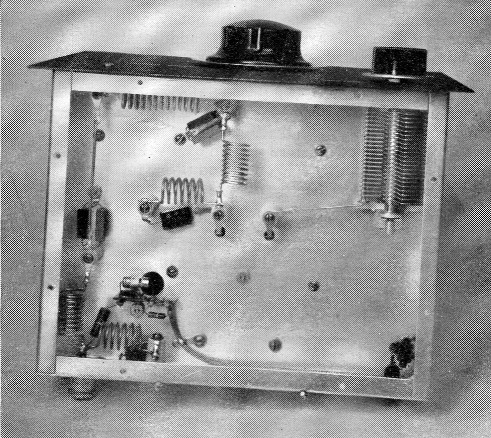
The arrangement of low-pass filter and voltmeter components is shown in this bottom view. An aluminum bottom plate goes on the chassis to complete the shielding of the filter.
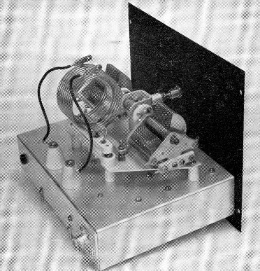
A side view of the coupler chassis. The Johnson clips are used sidewise to make a friction fit on soldering lugs used as taps on the coils and on the tuning condensers, a "quick-change" feature. The 6-32 spade bolts at the bottom of the rear wall of the chassis go through holes in the bottom of the cabinet and are fastened down with nuts after the assembly is in the cabinet; this holds the chassis firmly in place when a coil is pulled out of its socket.
Voltmeter circuit
The voltmeter circuit is connected to the input side of the low-pass filter, since this is the point at which the impedance can be set at a known value by means of a simple s.w.r. bridge. Also, harmonics generated by the rectifier circuit will be attenuated through the filter, which would not be the case if the voltmeter were connected at the output side. There is bound to be a small power loss through the filter and coupler circuit, so the voltmeter does not serve to measure the actual power delivered to the feeders. However, this loss is generally inconsequential and does not in any way impair the principal function of the voltmeter, which is to give a check on transmitter adjustment versus power output. Provided the adjustments of the antenna coupler are left fixed, an increase in the voltmeter reading always accompanies an increase in actual power output as adjustments are made at the transmitter. However, the voltmeter readings are not useful in determining the proper antenna coupler adjustments.
The circuit components are mounted as close as possible to the coax input terminal, but with as little stray coupling to the low-pass filter components as the circumstances permit. The r.f. voltage divider, R1R2, reduces the voltage applied to the crystal to a safe figure for the level of power to be handled. R3 is used as a combination r.f. filter (in conjunction with C9) and calibration resistor. Since a small amount of harmonic is generated in the rectifier circuit this filtering is desirable, as is also the shielded lead to the output jack. This lead is by-passed by C9, mounted right on its output end. RFC]. was found to be necessary to prevent fundamental-frequency current from flowing on the external lead to the milliammeter - this had some effect on the readings - and the end of the choke connected to J2 should not be by-passed.
The voltmeter is highly useful as a relative indicator even though not calibrated, and in such case the value of R3 should- be chosen simply to keep the reading on scale with normal power output. The value given in Fig. 1 was selected to make a 0-1 milliammeter with a 5000 ohm resistor in series read directly in r.f. volts in a 75 ohm load. The scale reading is multiplied by 100 for this purpose; that is, 1 mA corresponds to 100 volt r.m.s. The voltmeter can be calibrated by connecting the coupler to an antenna and adjusting to give a value of load at the input terminals equal to the impedance of the coax link, using an s.w.r. bridge for the purpose, and then measuring the r.f. current into the unit with a regular r.f. ammeter. As the power output of the transmitter is varied the current and voltage readings may be compared and various values of R3 tried until the readings are consistent with Ohm's Law. With a 75 ohm load, 1 ampere corresponds to 75 volts, % ampere to 37.5 volts, and so on. The power is simply PR or E2/R. Although the correspondence between the voltmeter and ammeter readings should be fairly close, once they have been made to agree at one point, small departures are to be anticipated, especially at low readings. It is hardly to be expected that the ammeter itself will be 100 per cent accurate, for that matter. However, it has been our experience that the readings are closely in line with what is to be expected from a normally designed transmitter.
Using the coupler
There is little to add to what has already been said many times about the adjustment of an antenna coupler or matching circuit. The procedure is fully described in the Handbook chapter on transmission lines. The principal difference here is that the coupling adjustments are reflected through the low-pass filter to the coax link. This is a negligible variation, since in the passband the filter shows the proper value of impedance at its input terminals - that is, the characteristic impedance of the filter - only when it is "seeing," at its output end, the same impedance. Proper adjustment is all-important, in view of the use of small mica condensers in the filter,(2) and can only be carried out with an s.w.r. bridge. The bridge shown in the photograph of the complete set-up is a quite inexpensive one (its construction is described in the chapter on measurements in the 1953 Handbook) and uses the 0-1 milliammeter in the December transmitter as an indicator. With the transmitter "test-operate" switch in the "test" position the r.f. output of the set is just about right to operate the bridge when the meter switch is set to "external voltmeter." On most bands this will give close to a full-scale reading. The exact reading with the bridge open-circuited is not particularly important for the purpose of adjusting the antenna coupler, since the object is to set for the line impedance - i.e., to get a good null - rather than to measure standing-wave ratio.
The total capacitance available in C6C7 as a balanced condenser (150 pF) is sufficient to cover a 2-to-1 frequency range under most circumstances, depending on the antenna and feeder system. This is convenient since it is not necessary to change coils when going to an adjacent band.
Including C5 in the coupler circuit makes adjustment considerably easier, as compared with an untuned link-coil circuit where matching depends critically on placement of taps on the antenna coil. In most cases the tap positions will not be very critical. A 300 ohm load can be transformed to either 75 or 50 ohm by manipulating the two condenser controls only, if the taps are 5½, 1½ and 1½ turns in from the coil ends on the 3.5-7, 7-14, and 14-28 Mc coils, respectively. The half-turns come about because the coils all have even numbers of turns so that the center can be grounded at the bottom, if desired.
The cabinet is 'not a necessary part of the coupler but is used simply for appearance and for mechanical protection of the unit. If used, the lid should be kept closed when making adjustments for matching the coax link, since the proximity of the lid and the antenna coil changes the inductance slightly, as compared with its value with the lid open.
Notes
- Grammer, "75 watt with an 'economy' power supply," QST, December, 1952.
- "Low-cost low-pass filters from standard mica condensers," QST, December, 1952.
George Grammer, W1DF.