"Q"-section transformers
Impedance matching with single and double sections.
Here is a very simple graphical method for finding the required impedance of a quarter-wave transformer or "Q"-section for matching between two given impedances. It can be used just as easily for determining the required impedances in a double "Q," an inherently broad-band matching system.
A quarter-wave section of transmission line has impedance transforming properties which are very convenient and simple to apply to amateur antenna practice. There are certain properties of these transformers, principally selectivity, which are not generally appreciated, however. Also, while the formula for the impedance of a matching section is simple, a graphical procedure, whereby the various impedances can more or less be "seen," should prove quite helpful.
To match two lines of impedances R1 and R2 we insert a quarter-wave section of impedance
Zo = √(R1 × R2). (1)
Mathematically, this means that Zo is the geometric mean of R1 and R2. Now if R1 and R2 were plotted on a logarithmic scale, the geometric mean would be halfway between the two, measured on a linear scale. Fig. 1 is plotted on a sheet of three-cycle semilogarithmic paper. The horizontal scale represents impedance and the three cycles (1 to 1000 ohms) cover the practical range of interest. The vertical scale is linear and enables us to find the geometric mean simply by drawing a straight line or by properly orienting a straightedge on the paper. A simple example is illustrated by line A, which shows that a 100-ohm "Q "-section will match a 33-ohm impedance to a 300-ohm impedance. When a design problem is at hand, the use of this chart permits a rapid search for a practical solution utilizing combinations of commercially available transmission lines or, in any case, lines of reasonable dimensions to construct. As we get into a discussion of "Q "-section selectivity and double "Q "-sections, the convenience of the semilog paper will become even more apparent.
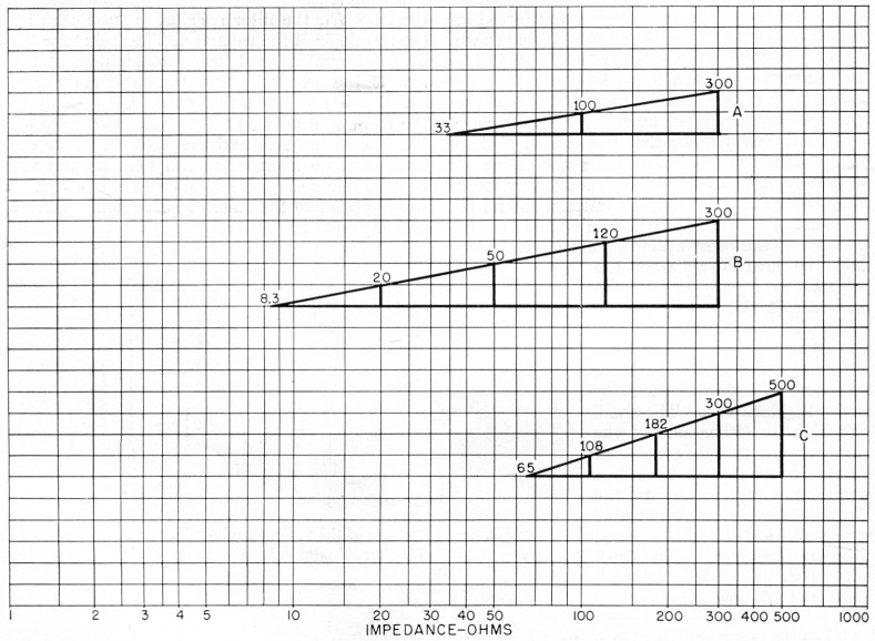
Fig. 1. Equal lengths along the calibrated scale of semilog paper give equal ratios; thus tue geometric mean of any two impedances can be found merely by drawing a straight line between the two values and dividing it into two equal parts. In the drawings above, the division is performed automatically by the vertical (linear) scale.
A common practice is to match a three-element beam to a 300-ohm line with a quarter-wave section of 50-ohm coax. When the radiation resistance of the beam is slightly over eight ohms, line Bon Fig. 1 shows this to be a perfect match at the design frequency. Tuning off the design frequency by even the small percentage bandwidth of the amateur bands produces a serious mismatch, however, since the matching section is then no longer a quarter wavelength. As would be expected, the greater the ratio between the impedances to be matched, the more selective the transformer appears. Fig. 2 shows the standing-wave ratio versus deviation from center frequency and the solid curve, labeled Ri/R2 = 32, 1/32, represents the present case where the ratio is 300/8.3 = 32. Fig. 2 shows the standing-wave ratio due to the quarter-wave transformer only; that is, the variation of the impedance of the beam itself with frequency is not included. Since beams are inherently quite selective the complete system is actually much more selective than Fig. 2 indicates.

Fig. 2. Effect of "Q"-section on selectivity, as expressed by the s.w.r. on the line to which the antenna is matched at the desired frequency, fo. As shown, the selectivity depends critically on the ratio of the two impedances to be matched. These curves do not include the selectivity of the antenna itself.
Incidentally, matching an 8-ohm beam to a 300-ohm balanced line with a 50 ohm coax transformer is not good engineering practice for reasons other than selectivity. Some of the current will be carried along the outer surface of the coax shield, resulting in difficulty from two standpoints. First, some of this energy will be dissipated by radiation, and secondly, the impedance of the transformer will not be the same as it would be if all the energy were confined to the inside dielectric region.
One possible solution to the selectivity problem is to use two quarter-wave transformers in cascade. If the impedance ratios are selected properly the reflection from one transformer can be made to cancel the reflection from the second transformer over a considerable bandwidth. This is not a new idea and is discussed in most modern transmission line texts.(1) The formula for the double section is
![]()
where Zo is the impedance of the section adjoining R1, and Zoo is the impedance of the section between Zo and R2 as shown in Fig. 3. The dashed curve labeled R1/R2 = 32, 1/32 in Fig. 2 shows the selectivity of this double "Q "-section and should be compared with the solid curve for the single-section transformer referred to previously.
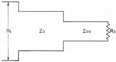
Fig. 3. Double transformer matching.
Equation (2), while rather simple looking, is quite inconvenient; but it still involves geometric means (three, in fact) and our semilog paper will do the trick. Line B in Fig. 1 was arranged so that the vertical linear scale divided it into four equal parts and it is immediately obvious that a 20-ohm "Q "-section will transform 8.3 ohms to 50 ohms and a second "Q"-section of 120 ohms will transform this interim 50 ohms to 300 ohms. The third geometric mean required by equation (2) is also satisfied in that the 50-ohm interim impedance is the mean of 8.3 and 300.
This may not be a very elegant solution to our original problem, however, since 20-ohm balanced line is rather difficult to realize, although five parallel sections of RG-22/11 (95-ohm twin-conductor coax) would be close enough. A more practical solution, although not involving double "Q "-sections, is to raise the impedance of the beam to 33 ohms by using a folded-dipole driven element and to match this to the 300 ohm line through a single balanced transformer consisting of two quarter-wave pieces of 50 ohm coax with the outer shields connected together. This match is illustrated by line A of Fig. 1 and, since 300/33 = 9, the selectivity is slightly narrower than that shown in Fig. 2 by the curve labeled R1/R2 = 8, 1/8.
A more appropriate example of the use of the double "Q "-section is shown in W8JK's excellent book on antennas.(2) In his Fig. 14-44, Dr. Kraus shows the standing-wave ratios versus frequency deviation, including the antenna variation, for both a single and a double transformer matching a 65-ohm dipole to a 500-ohm line (see Fig. 4). The transformer impedances required in these examples are shown by line C of Fig. 1. The selectivity of the single transformer alone is approximately the same as the Ri/R2 = 8, 1/8 curve of Fig. 2, over the same frequency range.
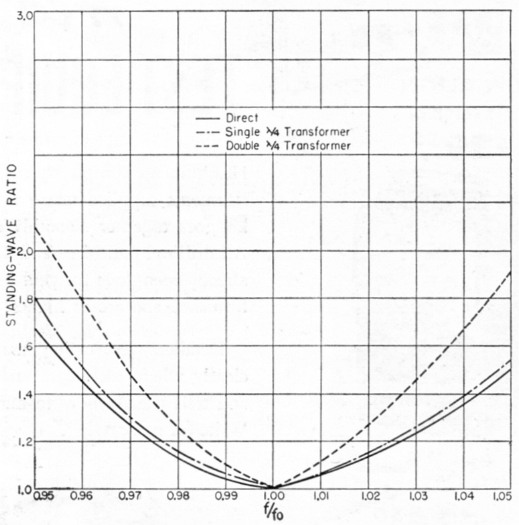
Fig. 4. A special case showing a 65-ohm antenna matched by a 65-ohm transmission line (solid curve) and to a 500-ohm line through single and double "Q" transformers. (Data from Kraus, Antennas, McGraw-Hill Book Co., N. Y.)
Notes
- Slater, J.C., "Mircowave transmission", pp. 57-62, McGraw-Hill book co.,Inc., New York 1942.
- Kraus, John D., Antennas, p. 437, McGraw-Hill Book Co., Inc., New York, 1950.
William B. Wrigley, W4UCW.