An isolating oscillator
Novel VFO circuit for 7 Mc.
VFO circuits can always be depended upon to start a lively discussion in any ham hot-stove league. The novel circuit discussed by W9JRO in this article should prove to be no exception.
When designing a conventional oscillator using an inductance and capacitance to determine the frequency, considerable effort must be expended in the design and construction of the tank circuit to make certain that it has a high Q. However, when this tank circuit is used in the oscillator, certain capacitances and resistances in the tube tend to impose a load on the tank circuit.
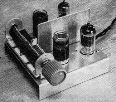
A VFO using electronic isolation between the tank circuit and the oscillator tube. A 5963 dual triode serves both as oscillator and isolating amplifier. It is mounted along with its tank circuit in front of the shield. The decoupling stage is placed at the rear of the chassis.
If the tank is placed in the plate circuit of the oscillator tube, the plate resistance of the tube and the plate-to-cathode capacitance load the tank: On the other hand, almost all oscillators draw grid current, so if the tank circuit is used on the input side of the oscillator tube the grid will offer the same kind of loading.
The oscillator tube reacts on the tank circuit in two ways. The resistance which the tube places in the circuit lowers the effective Q of the tank, and variations in the tube capacitances change the resonant frequency. Both of these effects contribute to instability in the oscillator. It is apparent that more stable oscillators could be built if the loading effects of the oscillator tube could be isolated from the frequency-determining tank.
The series-tuned Colpitts circuit(1) is an excellent step in this direction. The grid current is drawn from the low-impedance circuit formed by the two fixed condensers from grid to ground and the effective Q of the tank circuit remains very high. The tube capacitances are in parallel with the same fixed condensers. These are made large so as to minimize the effect on the oscillator frequency of any changes in the tube capacitances. These considerations in the design of the series-tuned Colpitts circuit yield an oscillator which has proven to be exceptionally stable.
There is an alternative method for achieving isolation between the tank circuit and the oscillator tube. The isolation may be achieved electronically by the use of a 100 per cent feed-back amplifier. Fig. 1 shows a block diagram of such an amplifier. Since all of the output is fed back with negative polarity to the input, the voltage gain of such an amplifier is very close to unity. However, there is considerable power gain.
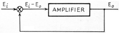
Fig. 1. A 100 per cent feedback amplifier can be used as an isolating amplifier because its input provides a very high effective impedance.
Suppose that the input impedance of the amplifier is called Z. Then, if there was no feed-back, the amplifier would draw an input current of
![]()
If the feed-back is present, the amplifier input voltage is reduced to Ei - Eo and the input current becomes
![]()
This is very small, since the output and input voltages are almost equal. Hence, the 100 per cent feed-back amplifier presents almost an infinite-impedance load to the source, and therefore it is well adapted to the problem of isolating a tank circuit from the oscillator tube. The Franklin oscillator, which this circuit resembles in some respects, does not make use of negative feed-back and therefore the tuned circuit is loaded heavily by comparison.
A simplified drawing of such a scheme is shown in Fig. 2. The isolating amplifier is used to couple the tank circuit to the grid of the oscillator tube. The grid current of the oscillator is supplied by this amplifier.
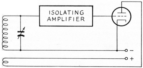
Fig. 2. A simplified diagram showing how an isolating amplifier can be used to reduce the loading effects of the oscillator tube on the tank circuit.
It is always necessary to feed energy into an oscillating tank circuit to sustain the oscillation. This is accomplished in Fig. 2 by the feed-back coil in the plate circuit of the oscillator tube. It is true that this couples some of the resistance and capacitance of the tube back into the tank circuit, but this is not as bad as it seems. The tank circuit is virtually isolated. If it is well insulated, and if the coil has low resistance, the Q will be high and the damping will be low. This means that only a small amount of energy need be fed back into the tank circuit to maintain oscillation. It is not necessary to couple the plate coil tightly to the tank circuit and the effect of the oscillator tube is minimized.
There is a direct analogy between the plate coil in this circuit and the two fixed condensers from grid to cathode and cathode to ground in the series-tuned Colpitts circuit. In each case this is the manner in which energy is fed back from the tube to the tank circuit and in each case this is the place where changes in the tube can cause fluctuations in the oscillator frequency.
It is possible to make certain general comparisons between the circuits concerning this point. The energy fed back in the series-tuned Colpitts circuit depends on the capacitance of the variable condenser used for tuning. If this capacitance is too low, there is insufficient feed-back and the circuit will not oscillate. Therefore, the stability varies with frequency. In the isolating oscillator, the energy fed back tends to be more nearly constant over the range of an average-size condenser.
In the series-tuned Colpitts circuit the grid-tocathode and cathode-to-ground tube capacitance form part of the resonant circuit and can affect the oscillator frequency. In the isolating oscillator only the plate-to-ground capacitance of the oscillator tube is coupled into the tank through the plate coil. This does not contribute greatly to frequency instability unless the tube is operated at excessive plate voltage.
The proper values for the fixed capacitances from grid to ground in the series-tuned Colpitts have been reasonably well determined. The degree of coupling for the plate coil in the isolating oscillator must be found by experiment. This should not be considered difficult, since it need be done only once in the lifetime of the oscillator.
It is well known that the major cause of frequency drift in a VFO is the physical distortion of the tank coil as a result of the heating effect of the tank current. In the isolating-oscillator circuit, the tank current can be very small, since the amount of power that need be supplied to the isolating-amplifier input circuit is negligible because the grid does not draw current. On the other hand, in the series-tuned Colpitts circuit, the grid excitation is derived from the voltage drop across the large capacitance from grid to cathode. To develop sufficient excitation, it is therefore necessary to have a relatively high circulating current in the tank circuit.
An oscillator has been built to demonstrate the above principles and is shown in the photograph. It uses miniature tubes and has small dimensions so that it can be used to replace an unsatisfactory VFO in existing equipment. The circuit appears in Fig. 3. The VFO was designed to operate in the 40-meter band and has a frequency range from 6.7 to 7.5 Mc.
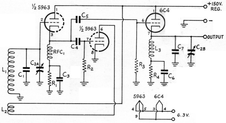
Fig. 3. Circuit of a practical isolating oscillator.
| C1,C4 | 82 pF zero-temp. ceramic. |
| C2 | Dual midget variable, 30 pF per section, double-spaced (Hammarlund HFD-30-X). |
| C3 | 1 nF mica. |
| C5 | 10 pF mica. |
| C7 | 50 pF mica. |
| R1 | 4.7 kΩ, 2 watts. |
| R2 | 33 kΩ, 1 watt. |
| R3 | 22 kΩ, 1 watt. |
| R4 | 2.2kΩ, 2 watts. |
| L1 | 20 turns No. 18 d.s.c., ¾ inch diam., close-wound. |
| L2 | 5 turns No.18, turns double-spaced, wound ¼ inch from L1 on same form. |
| L3 | 25 turns No. 18, ¾ inch diam., turns double-spaced. |
| RFC1 | 2.5 mH r.f. choke. |
The isolating amplifier is of the simplest possible type - a cathode follower using half of a 5963 dual triode. The grid bias is derived from a cathode resistor, R1, and this is made somewhat larger than usual to make certain that the grid will never go positive and draw current through the tank circuit.
The other half of the 5963 is used as the oscillator. The small coil in the plate circuit, L2, is wound in the same direction as the coil in the tank circuit and is placed at the grounded end of the tank. A 12AU7, 12AT7, or 12AX7 can be used in place of the 5963 without any change in wiring. However, it can be shown that the output of the VFO will decrease as the amplification factor of the tube increases. The position and number of turns in the plate coil should be adjusted for maximum frequency stability if different types of tubes are used.
In order to isolate the VFO from the load, a 6C4 is used as a cathode follower to provide the output. A resonant circuit, C7C2BL3, is used in the cathode of the 6C4 to provide as much power gain as possible in this stage. Ganged tuning is used for the sake of convenience. The shielding between the two resonant circuits is not needed to prevent oscillation. It is used to decouple the output from the tank circuit which determines the frequency.
The output of the unit is sufficient to drive a tube of the same size as that used in the oscillator.
The frequency characteristics of the unit are excellent. After a ten-minute warm-up, the drift was found to be around 10 cycles for the next five-minute period. After a half hour of warming up, the oscillator was adjusted to zero beat with a crystal oscillator. An hour later there was no detectable beat. This is very good performance for a 7-Mc. oscillator.
The unit was compared directly with a series-tuned Colpitts circuit for voltage sensitivity. The same power supply was used for each. The electronically-isolated oscillator had a sensitivity of 22.5 cycles per volt and the series-tuned Colpitts had a sensitivity of 5.6 cycles per volt. This indicates that the unit should preferably be supplied from a well-regulated voltage source. The voltage sensitivity might be reduced by using a multistage feed-back amplifier in place of the isolating cathode follower, or by using a pentode in place of the triode for the oscillator tube. In spite of the increased voltage sensitivity, keying characteristics do not appear to suffer in comparison with the series-tuned circuit, and the stability against mechanical vibration is good.
The basic circuit shown in Fig. 3 can be adapted easily to larger tubes if greater output is desired. There is no need to use a dual triode. Different types of tubes can be used in the isolating cathode follower and oscillator, but care must be taken that the isolating amplifier is sufficiently well biased and has large enough power capabilities to drive the grid of the oscillator tube without drawing grid current itself.
The resonant circuit in the cathode of the output cathode follower may be eliminated with some sacrifice in output. An r.f. choke must be inserted in place of the coil. The cathode circuits in the two cathode followers will then be identical, except for a possible change in the size of the biasing resistor.
In most cases it will not be wise to substitute an amplifier or doubler for the second cathode follower. Either of these may draw grid current and this tends to load the cathode circuit of the isolating cathode follower. If this loading becomes too great, the isolating amplifier may be forced to draw grid current and defeat its purpose.
Notes
Richard Clay, W9JRO.