Let's listen
Hints on using and understanding receivers.
If you don't understand just what your receiver is doing for you as you twist the dials and knobs, don't worry - you are not alone. But by not understanding you are probably not utilizing your receiver to best advantage. This is an article aimed at giving you some comprehension, in as non-technical language as possible, so that you can make your receiver work for you.
All too many amateurs work havoc on the family budget to garner the necessary shekels to buy a super-duper receiver and never get their money's worth because they fail to utilize the receiver to its full capabilities. If the amateurs who have never read their receiver instruction books were laid end to end, they would probably stretch from here to Tibet. If you are one of the hams who has never studied his instruction book, get it out sometime (if you lipan still find it!) and read it from cover to cover.
In this article we will try to pass along some ideas on uses of your receiver that will improve your operating enjoyment. But before getting into the actual handling of the receiver, let's take a minute to consider something else. An important point that is sometimes overlooked is the location of the receiver on the operating table. In c.w. work, right-handed operators often find it more convenient to have the receiver tuning knob placed a little on their left, while the right hand operates the key or bug and any switching arrangement. The most convenient height for the tuning knob is usually four to eight inches above the table top. You can find the best height to suit your particular needs by the placing of books under the receiver until you reach the most restful spot for your left hand and arm. Once the proper height is determined, it is a simple matter to build a small shelf to fit under the receiver. Incidentally, the space under the shelf makes a good spot to keep your log.
While on the subject of operating convenience it might be well to talk about the knobs on a receiver. Many times manufacturers design these with an eye toward beauty and not toward convenience. A good example of this is the use of small tuning knobs. It is no great problem to replace small knobs with larger ones, and it will be found that it is considerably easier to handle a receiver with a large tuning knob than with a small one. Some receivers don't have enough bandspread to suit their users. The tuning ratio can be increased in the order of 5 to 1 by installing a vernier type drive for the bandspread control. The writer has used a National type AM drive on a receiver and it was a great improvement over the original control. In cases where insufficient panel space prohibits the use of this type of drive, small 5-to-1 planetary drives are available that can be used. They don't look pretty, but they work fine.
The speaker can be placed either above or below the table, depending upon space requirements. If it is placed on top of the receiver there is a possibility of acoustic feed-back. Acoustic feed-back is caused by the vibration of the speaker making the receiver chassis vibrate and thereby producing a signal in the receiver's audio system. The signal is then passed along to the speaker, making the whole set-up unstable. There seems to be a tendency in the last few years for amateurs to depend more and more on speakers and less on headphones. With the exception of high-fidelity crystal headphones, nearly all other types are more selective than speakers, and selectivity is probably the most important feature of any receiving set-up in these days of crowded bands. When listening with a speaker, the ears must often contend with outside noises that cut down 100 per cent copy. Though the grunts, squeals, whistles and other assorted noises issuing from a speaker may be the sweetest music this side of heaven to a ham's ears, the family nerves and relations are inclined to become a bit strained by prolonged sessions. Give headphones a "thirty-day trial;" you'll be copying more than you ever did with a speaker.
Antenna-receiver matching
When Joe Ham puts up an antenna system he wouldn't for a minute think of using it without first matching it to the transmitter. Whether it is with an antenna coupler or just by swinging the link in the final amplifier tank, it still must be adjusted. However, few hams give the same consideration to coupling the input of the receiver to the antenna feedline. They expect the receiver to produce good results whether they use a few feet of wire or an elaborate array. The receiver should be properly coupled to the feed line for the receiver to give its maximum performance. This is particularly true at 14 Mc. and above. Proper matching can be obtained by using an antenna coupler such as described in the receiver chapter of the Handbook. Antenna couplers are not always necessary, of course, but they are simple and worth a try.
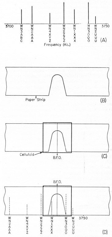
Fig. 1 - An illustration of some of the principles of receiver operation. At some given time, the 80-meter Novice band might look like A, the vertical lines corresponding to the signals of the calls given below.
The receiver can be represented by the strip of paper shown at B - laying it over the "band" at A allows some signals to be "seen" (heard) through the "window" while rejecting all others. Tuning the receiver corresponds to moving the strip from right to left or vice versa.
The b.f.o. corresponds to the celluloid slide shown in C. Its position can be changed relative to the paper strip, but it moves along with the paper strip.
Laying the paper-and-celluloid of C on the "band" of A gives the picture in D, where the signal from WN1XXX is the only one that can be heard.
Receiver tuning
In visualizing what your receiver is doing, let's try a simple but accurate picture. For our purposes, we are going to "look" at a portion of the 80-meter band, the 3700-3750-kc. Novice section. In Fig. 1A, we see this frequency range with the various signals represented by vertical lines, the higher lines being the stronger signals. The receiver (with the b.f.o. turned off) can be represented by the paper strip in Fig. 1B, the " window" representing the "selectivity" or "passband" of the receiver. If this strip is cut out and laid across the "band" in Fig. 1A, moving it across the band will allow you to see whatever signals fall in the open window. One that falls in the center of the window will be passed at full height (strength), but one near either side of the window may have part of it cut off (attenuated), depending upon how close to the edge it falls. Moving the strip across the band is just the same as moving the tuning dial of your receiver - the receiver passes the signals that fall under the window and it rejects all ethers. A signal in the center of the window comes through at full strength - one near the sides will be attenuated. Obviously, if the window were made narrower, it would see fewer signals for any given position - this corresponds to a receiver with more selectivity.
But these c.w. signals are not readily audible unless the b.f.o. (beat-frequency oscillator) is turned on, as a moment's trial with your receiver will prove. The b.f.o. is represented in this example by a celluloid scale slipped over the paper strip, as shown in Fig. 10. A line marked on the celluloid represents the beat-oscillator frequency. Moving the celluloid on the paper scale is the same as twisting the b.f.o. control on a receiver - it changes the relationship between the b.f.o. frequency and the signals coming through the receiver when the tuning knob is left in one position. But when the tuning knob is turned (sliding the paper scale across the band), the celluloid rides along with it, and the apparent relationship between b.f.o. frequency and the signals is also changed. However, the relationship between the b.f.o. and the "window" is not changed.
Now we have to digress for a minute and consider what the b.f.o. does. Because there is no modulation on a c.w. signal, the signal must be made audible in some way. You know from listening in a crowded phone band that two adjacent carriers generate on audio tone called a "heterodyne." The tone of this heterodyne (or "beat note") depends on the separation in cycles between the two carriers - a separation of 1500 cycles gives a 1500-cycle beat note. By introducing a second signal in the receiver (the b.f.o. output), we can set its frequency relative to an incoming signal to give an audible beat note of any frequency we wish.
Getting back to the paper and celluloid, it is obvious that as we tune across the band (move the paper scale) the relationship between the b.f.o. and the received signals changes. The frequency difference between the b.f.o. and the received signals determines the tones of the beats we hear. When the b.f.o. and incoming signal coincide, there is no frequency difference, and this is called "zero beat." Changing the relationship in either direction gives an audio tone.
Take, for example, the condition shown in Fig. 1D. The signal from WN1XXX passes through the receiver (window) and all others are rejected. A low-frequency beat note is obtained from WN1XXX. As we tune the receiver slightly in one direction (to the left, for example), the beat from WN1XXX will become lower. Tuning in the. other direction, the signal from WN1XXX will become higher in pitch and weaker, and we will begin to hear WN3OOO weakly with a high-pitched signal. Tuning far enough to the right would put WN1XXX out of the window, and the only signal to be heard would be WN3OOO. With WN3000 centered in the window, we would still have control of the beat note at which we heard him, simply by changing the b.f.o. setting.
Notice that tuning through any given signal, with the b.f.o. set somewhere within the confines of the passband (window), we start with a high-frequency beat note, gradually work down to zero beat, and then go up to a higher one until the signal disappears. Thus there are two settings of the receiver tuning that give the same audio output tone on any signal. There is actually only one signal present, but we can hear it at two places. If you arbitrarily say the signal is at one of these points, the other one is called the "audio image."
C. W. tuning
To set up the receiver for c.w. reception, the b.f.o. should be turned on and the a.v.c. (automatic volume control) should be off. The manual gain control (marked "Gain" or "Sensitivity" or "RF.") should be operative - sometimes it is tied in with a switch, and this is where the instruction book can set you straight.
The audio gain is usually set higher than with phone reception. The sensitivity control is then used to control the strength of the incoming signals.
Many beginners are inclined to run the sensitivity control wide open and, in doing so, cause strong signals to block or overload the receiver. The r.f. control should be kept at a low enough setting to avoid such blocking but high enough to hear the "weak" ones. A little practice will determine the best setting. There is a limit to what any receiver will do, and there will be times when a strong signal is too close in frequency to a weak one to permit reception of the weak one. The more selectivity the receiver has, the better it will be in dragging weak signals out from under strong ones.
Crystal Tuning
There are two schools of thought on how selective a receiver should be. One group holds that the more signals you hear at any given moment, the better chance you'll have to hear stations that want to break in. This is particularly true in traffic nets where all stations are close together but not on exactly the same frequency. The other group feels that there is no such thing as "too much" selectivity. In these days of crowded bands they are interested in "pinpoint" reception only, striving more and more for QRM-free contacts. Without taking sides, methods of receiver tuning with more selectivity will be discussed.
Many times two signals close together and of the same signal strength make reception of either signal difficult. By varying the b.f.o. pitch control, it is sometimes possible to make either signal distinctive enough to be "good copy." If your receiver has a crystal filter it should be used whenever the QRM becomes bad. Learning to use the crystal filter will take some time and patience, but will repay you many times over in more solid copy.
With the receiver set up for c.w. reception find a good solid c.w. signal, preferably a commercial station that you know will be transmitting steadily. Turn the crystal to its sharpest position and carefully tune across the signal. You will notice that one side of the signal is stronger than the other. Tune to the stronger side and set your b.f.o. for the most pleasing note to your ear. Check the crystal position to make sure it is at its sharpest tuning. Now tune to the weaker side of the signal and adjust the crystal phasing control until the weak side either disappears or is phased to its weakest possible point, Your receiver is now operating at its maximum possible selectivity. It will surprise you to find how many more "solid" contacts can be made by making use of your crystal filter.
Going back to our visual indication of what happens in a receiver, Fig. 2 shows how a crystal filter can change the shape of the "window" to exclude unwanted signals. With the crystal in the "shstrp" position, a rejection notch appears in the window. The crystal phasing control varies the placement of the notch and if it is tuned properly, the audio image can be notched out leaving only one side of the signal audible.
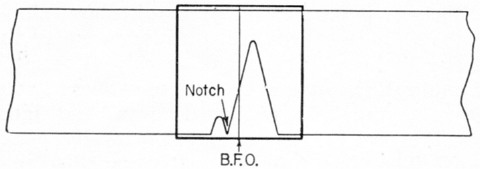
Fig. 2. When a crystal filter is used, the passband (window) is made narrower, thereby increasing the selectivity. The phasing notch is useful for eliminating the audio image or an interfering signal.
Phone tuning
In tuning and listening to phone signals, the receiver is operated differently than for c.w. The a.v.c. is turned on, the b.f.o. turned off. Let's explain a.v.c. so we get a picture of what it accomplishes.
Automatic control of gain of a receiver is a distinct operating convenience in the reception of phone signals because it tends to keep the output level of the receiver constant, regardless of the input signal level. This is accomplished by taking a voltage developed by the received signal in the detector circuit and using this voltage to control the gain of several stages in the receiver. Since this voltage is proportional to the carrier amplitude of the incoming signal, the receiver gain is reduced as the input-signal strength increases.
In tuning in phone signals in crowded bands, the crystal filter may be required to reduce interference. Careful adjustment of the phasing control will help cut down heterodyne QRM, one of the most common interference problems on the phone bands. The setting of the crystal for phone is very similar to c.w. except that it may not be possible to use the "sharp" position and still keep phone signals intelligible. Crystal filters in different types of receivers have different characteristics, but a little practice will soon determine the best settings.
S.S.B. reception
For the reception of single-sideband signals a tuning procedure very similar to that of c.w. is used. Turn a.v.c. off, b.f.o. on, m.v.c. on and set the audio control at a high level. The r.f. gain control is reduced to the lowest level possible that will allow hearing the s.s.b. station. The receiver is tuned carefully to the signal and the b.f.o. pitch control is varied until the s.s.b. station becomes intelligible.
Without going into great detail about single sideband, it is a form of transmission where the carrier and one sideband is sharply attenuated or reduced. Because of the lack of carrier at your receiver, your b.f.o. is turned on and the signal from it is used for the carrier of the received s.s.b. signal. The pitch control must be varied so that the inserted carrier is in the proper relation frequency-wise to the sideband.
The various settings of the receiver controls for receiving different types of signals are summarized in Table 1.
| Signal | B.F.O. | A.V.C. | M.V.C. | Audio | R.F. | B.F.O. pitch | Crystal and cryctal phasing |
|---|---|---|---|---|---|---|---|
| C.W. | On | Off | On | High | Vary to signal level | Vary for pleasant tone | As needed |
| Phone | Off | On | Not used | Comfortable | Full on | Off | As needed |
| S.S.B. | On | Off | On | High | Vary to signal level | Set carefully for best intelligibility | As needed |
As any DX man will tell you, it isn't always true that "if you can hear 'em, you can work 'em," but at least you'll be in a much better position for making contacts when your receiver is being handled properly.
Lewis G. McCoy. W1ICP.