Voice controlled break-in circuit
| C1 | 1 nF |
| C2 | 100 nF |
| C3 | 10 nF |
| C4 | 250 nF |
| C5,C6 | 5 nF mica |
| C7,C8 | 20 µF 150 volt electrolytic |
| R1 | 500 kΩ volume control |
| R2 | 470 Ω |
| R3 | 100 kΩ |
| R4,R5 | 500 kΩ |
| R6 | 1 MΩ |
| R7 | 3.3 kΩ |
| R8 | 100 Ω |
| R9,R11 | 10 kΩ |
| R10 | 1 kΩ |
| R12 | 10.6 kΩ |
| R13 | 470 Ω, 2 watts |
| K1 | Sensitive relay |
| S1 | S.p.s.t. toggle "tune-up" switch |
| T1 | Small 6.3 volt filament transformer |
Don Kinney, W8FSA of Ithaca, Mich., uses a break-in circuit with a couple of neat twists. Shown in Fig. 1, it uses two dual tubes and a relay for the major components. One half of a BAL5 is used for the speech rectifier, while the other half is used as the negative-supply rectifier for biasing or cutting off a couple of stages in the exciter. The 6BA7 mixer and the 6AG7 amplifier grids sit at around -100 volts with no speech, but when the relay closes (or when Si is closed), the 6BA7 grid drops to -1 volt and the 6AG7 grid goes to -11 volts, with the constants shown. Other operating biases would require other values of Rs, Rio and Rue, of course. The only restriction to the system is that the controlled stages do not draw grid current in operation, since the bias voltages would vary.
The pull-in voice level is set by R1 - the hold-in time is dependent upon the C4R5 time constant. It will drop out faster if C4 (or R5) is made smaller.
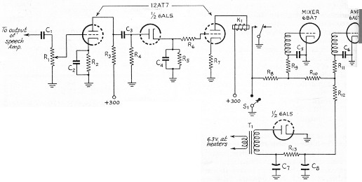
Fig. 1. The voice-controlled break-in circuit used by W8FSA.