Improving the series noise limiter
Simple circuit changes for better performance.
Any amateur plagued by automobile-ignition interference will welcome an improved noise-limiter circuit. Here W3BLC shows a simple modification of a widely-used series-limiter circuit that is well worth the slight effort involved. It should be particularly interesting to anyone operating mobile.
Several years ago I became interested in putting a noise limiter in my BC-348. Friendly amateurs and engineers were only too happy to disclose their pet circuits, and each scheme was duly installed and evaluated. The results with all of them were pretty much the same, with one exception. In operation this particular circuit not only limits the noise peaks but seems to remove the remaining "stumps." After using it for a couple of years and recommending its use to all my friends, I felt ashamed at not having taken time to pass it along to the remainder of the amateur fraternity, so that anyone who wanted to might enjoy its use.
The circuit is shown in Fig. 1, and it can be seen that it closely resembles one of the series-limiter circuits carried in the Handbook. Actually, it differs only in the feed-back path of the cathode of V1 to the cathode of V2, and this change calls only for one additional component. But it is this feed-back path that seems to do the trick of changing it from a conventional limiter to a real limiter. Several of my friends had expensive commercial receivers with conventional series limiters in them and, after changing over to this circuit, reported the receivers sounded like new sets. The boys operating on 10-meter 'phone will find this circuit excellent for eliminating ignition interference. One of my friends operating near the end of a bus line reported 99 per cent operating capability after installing the new limiter circuit. Previously, each QSO was interrupted by idling busses, while the drivers went out for their smokes.
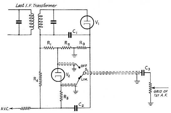
Fig. 1. Circuit of the improved series limiter.
The dual diode used in the circuit can be a 6H6 or 6AL5, or any other type that has cathodes brought out separately. Crystals were tried in the circuit but do not operate successfully. In the original circuit, as passed along to me, R3 was shown as a 50,000 ohm potentiometer, but after weeks of adjustment I decided there was little or no improvement with changes in the value, and a 6800 ohm fixed resistor was substituted. This value is not critical, and anything from six to nine thousand ohms works satisfactorily. The audio volume control should be one megohm or higher. It is obvious that considerable loss in audio voltage is inherent with this circuit, but most receivers have twice as much as they normally need, so this is no serious drawback. To eliminate "tweets" at multiples of the intermediate frequency, it is advisable to shield the "hot" i.f. leads, keeping C1, R1 and R4 enclosed by a small metallic cover and the leads short. This is just good receiver-design practice. If the switch Si is located remotely from the last i.f. transformer can, the leads to and from it should be shielded to cut down hum pick-up in the receiver. In my BC-348 I put this switch in one of the 'phone-jack holes, thus necessitating a long run around the chassis, but the hum pick-up from heater leads was completely eliminated by the shielding. I mounted the 6AL5 under the chassis on a little bracket near the terminals of the last i.f. transformer. For my money, the limiter could be permanently wired in the circuit. The only time I use S1 is to demonstrate the limiter.
For the record, this limiter, like all series limiters, does not show any appreciable improvement when operating on c.w. with a heavy b.f.o. signal swamping the second detector. However, when you use it on phone it's a "honey."
H.O. Lorenzen, W3BLC.