The antenna coupler helps the receiver, too!
Any amateurs do not give adequate attention to the most efficient means of coupling the receiver to the antenna. Where an antenna coupler is used, the antenna feeders are usually connected to the receiver by means of a single-pole double-throw relay in each feeder line, if balanced feeders are employed, or by a single-pole double-throw relay if coax is used. Sometimes an untuned pick-up coil is coupled to the tuner tank coil.
After completing a wide-range coupler with B & W type TVL coils, various means of coupling the receiver coax input to it were tried. The pick-up coil was tried because it offered flexibility for all-band operation with the possibility of eliminating costly relays. Because of the low-impedance coax input to the receiver, the pick-up coil, which was loosely coupled to the tank coil, required series tuning by a variable condenser. A 100 pF tuning condenser was incorporated in the coupler, mounting it beneath the main chassis so as to be out of the direct field of the tank inductance and yet be adjustable from the front panel of the coupler by means of a knob.
A small d.p.s.t. normally-closed relay opens the receiver antenna and B+ during transmitting periods. A small coax relay is preferable for the antenna switching.
The advantages of this means of coupling the receiver to the antenna are obvious. The proper impedance match between antenna and receiver is readily obtained. The coupler tank is, as usual, tuned to the desired frequency. By adjusting the series variable condenser, the receiver input circuit is tuned to the same frequency. The condenser tuning is not critical and need not be varied over any one band.
The relay is mounted outside the coupler housing as indicated in Fig. 1. This is desirable as no supply lines enter the coupler housing and thus no r.f. is induced in the relay-solenoid windings and possibly the supply lines.
| C1 | 100 pF variable. |
| L1 | 3.5 Mc - 35 turns, 1_3/8 inche long. 7 Mc - 19 turns, 1 inch long. 14 Mc - 8 turns, ½ inch long. 28 Mc - 4 turns 3/8 inch long. All coils wound with No. 26 enameled wire, 1½ inche diam. (National XR-6 forms). |
| L2C2 | Usual transmitter antenna-coupler coil and condenser. |
| K1 | D.p.s.t. normally-closed relay (coax type preferable). |
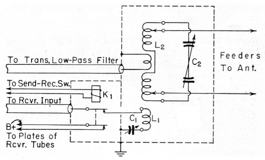
Fig. 1. A separate link and coax line is provided for receiver input.
The appropriate receiver pick-up coil is plugged in place with the tank coil for the desired band. A combination arrangement can be constructed in which the pick-up coil and tank inductance are integral so that both may be plugged in as a unit.
With C1 tuned to resonance, a gain of six S units has been observed over the nonresonant condition, or with the condenser shorted.
John J. Glauber, W3GQD.