Wide-band re-entrant networks
A solution to the problem of amateur antenna loading.
Antenna coupling and transmitter loading have always been confusing to many amateurs, and this article is intended to help in that direction. The mathematics has been edited out, in an effort to make this a "non-technical" article in every sense of the expression.
Many times in amateur activities, it is taken for granted that a job can be finished. At this writing, it is by no means certain that the study to be described has been brought to any degree of conclusion.
Like many others, we have often been faced with the problem of loading the final properly. Many methods have been tried, and we have had some measure of success.
A new circuit
About one year ago, a new output circuit was evolved from a series of experiments. It is shown in Fig. 1. It became immediately evident that this circuit has great flexibility. Adjustments were found to be quite critical with regard to the type of antenna in use, but at the same time almost any variation of loading could be bad.
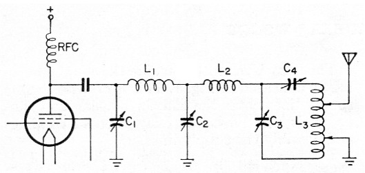
Fig. 1. The "pi-ip" antenna-coupler circuit uses a few more components than usual, but results in a much wider range of possible adjustments.
It will be noted by some that the combination L1, C1, C2 resembles the familiar pi network. Reference to the Handbook and other articles will show that this circuit has great versatility of itself. The added elements, L2, L3, C3 and C4, develop an imaginary impedance that can be considered to be the reverse of that of the "pi" network. It has therefore been aptly named the "ip" network,(1) to distinguish its function from the more usual parts of the circuit. Referring now to Fig. 1, we see that, without leaving any critical component values, at least five variable elements have been introduced into the over-all adjustment procedure. Assume that the setting of C3 is at some arbitrary value, then L2, C3 and the lower part of L4 up to the ground tap becomes a series-resonant circuit, which can absorb considerable power and pass it to ground at the particular frequency. This has proved to be a rather mixed blessing at times as the curves to be given later will show. Thus, the setting of C3 has considerable effect.
At the same time, the coil L2, together with C4, and the upper portion of L3 down to the antenna tap, must be considered a series-resonant circuit capable of conveying some power to the antenna. This is considered desirable. However, it has been found that we must be careful to tune to the proper frequency.
Looking at the "ip" network as a whole, C3, C4 and L3 form a network having parallel-resonant characteristics. Its tuning will be affected by C3 and C4 and also the setting of the taps on L3 and the loading presented by the antenna system. One begins now to see the flexibility built into the combination as it has evolved. Since L3 can be made plug-in, its value can be any reasonable one, and the taps can be placed anywhere on the coil.
Applications
Let us now come to the application of this circuit and evaluate results in practical terms.
It was found, at first, that most of the possible-adjustment combinations resulted in curves such as shown in Fig. 2. The point where resonance was obtained for the final resulted in very light loading in the desired band. Some adjustments, of course, were found that gave very high loading. Most of these, however, gave very poor results and, after much testing and measurement, it was found that the trouble was an overly large fraction of the available r.f. flowing into L2, C3, and L3 and going to ground. As this trouble had occurred often before with many types of output circuits, no special blame was put on the "ip" network, but precautionary procedures to guard against this condition must be used.
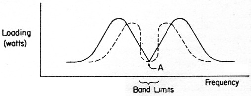
Fig. 2. Improper tuning of the "pi-ip" coupler will result in a "V" (solid line) or "M" (dashed line) characteristic. The point of minimum loading, marked "A," is called the "trap" or "suck-out" point, and is to be avoided.
At the present time, some experience has been gained in the adjustment of the "pi-ip" net to permit very useful operation. Fig. 3 is representative of the best results obtained so far. If the adjustment gives too flat a "top" to the curve, the best results will fall outside the band. However, because of the interacting nature of tuning C3 and C4, the width of this flat top can be controlled.
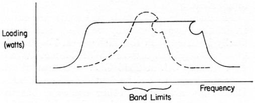
Fig. 3. Proper tuning gives a broad coupling characteristic or a narrow one (dashed line), either of which can be adjusted to fit the band.
Results
When we began to get good reports using our newly-developed system, we then took several very exact plots on the frequency response using an ancient-but-accurate R-meter in combination with a Quite Stable Amplifier No. 5 built by a noted amateur manufacturer many years ago. S-meter readings could be expected to give comparable results.
All conditions of tuning that gave good reports turned out to conform with the curve shown in Fig. 4, the ideal of Fig. 3. The peculiar shaping of this curve and the unusual means of accomplishing it resulted in its being called the "S9" curve. In achieving this we believe we have found what many amateurs are seeking.
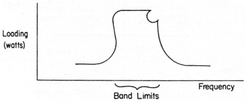
Fig. 4. Perfect tuning of the coupler gives uniform loading across the entire band, with the exception of a residual suck-out point at the high-frequency end. In practice this is not too important.
This article has been hastily prepared so that as many as possible could take advantage of the experience gained so far. It is to be hoped that, in the neat, future, we can present a few more exact figures on performance and on the components to be used. In the meantime, we hope that every amateur station will report on its results with this loading method.
Full credit is given those amateurs in daily association with the author for the inspiration necessary for this article.
Notes
- Strictly speaking, an imaginary of this type calls for a j factor, and should therefore be written "jip." However, the j is omitted here in the interests of simplicity. - ED.
Wilburn D. Fingers, WK4ZY.