The "little firecracker" linear amplifier
A pair of 6146s and good s.s.b. design practice.
The "Little Firecracker" s.s.b. linear uses two 6146s in parallel. It operates on 80 through 10 meters without lifting the lid, and all power supplies are housed in the same cabinet as the r.f. components.
Amplification of the output of any low-powered s.s.b. exciter can be done only by using a linear amplifier. A linear is an amplifier so adjusted that its output voltage is proportional to its input voltage. Use can be made of Class A, AB1, AB2 or B - Class A is generally used for very low power levels, as in the exciter output stage.
Not only do we want to amplify our s.s.b. signal, we want to amplify it without adding new and possibly undesired signals. If the unwanted sideband is 40 dB down in the signal coming from the exciter, we expect the same (or very close to the same) ratio in the antenna after amplification. We want no intermodulation products added that will either degrade the desired sideband or appear as "crud" outside the side-band. In short, we want a really "high-fidelity" amplifier for r.f. As in audio work, you can't expect a good linear to clean up a degraded signal fed to its input. That's expecting too much.
Desirable characteristics of any linear amplifier include:
- Good linearity up to the power-handling limit of the tubes.
- High power sensitivity.
- Multiband operation without opening the cabinet.
- High-Q LC circuits.
- Constant-voltage plate, screen and grid supplies.
- Stability.
Linearity and output
It should be recalled that the figures given for audio service in Class A, AB1, AB2 or B can be used for r.f. linear amplifier used with s.s.b. suppressed carrier. Two tubes can be used in parallel or push-pull - we elected to use two tubes in parallel, for circuit simplicity. In push-pull or parallel, however, it is desirable to use tubes with similar characteristics so that the tubes will share the load equally.
Table 1 gives the Class AB1 and AB2 ratings of the 6146, an excellent tube with a plate-dissipation rating of 25 watts. Slightly more output can be obtained in Class AB2 operation, although running the tubes in Class AB1 (no grid current) simplifies the driver problem and greatly reduces the chances for distortion on signal peaks in the grid-current region. In s.s.b. suppressed-carrier operation the maximum screen voltage (250) can be used, resulting in higher power sensitivity and slightly more peak output. The "maximum-signal d.c. plate current" is not what your meter reads on speech.(1)
| A.f. power amp. & mod. | AB1 | |
| D.c. plate voltage | 750 V | |
| D.c. grid No. 2 screen voltage | 200 V | |
| D.c. grid No. 1 control grid | -50 V | |
| Zero-signal d,c. plate current | 57 mA | |
| Maximum-signal d.c. plate current | 227 mA | |
| Zero-signal d.c. grid No. 2 current | 1 mA | |
| Maximum-signal d.c. grid No. 2 current | 27.5 mA | |
| Maximum-signal driving power (approx.) | 0 W | |
| Maximum-signal power output | 120 W | |
| A.f. power amp. & mod. | AB2 | |
| D.c. plate voltage | 750 V | |
| D.c. grid No. 2 screen voltage | 165 V | |
| D.c. grid No. 1 (control grid) voltage | -45 V | |
| Zero-signal d.c. plate current | 35 mA | |
| Maximum-signal d.c. plate current | 240 mA | |
| Zero-signal d.c. grid No. 2 current | 0.6 mA | |
| Maximum-signal d.c. grid No. 2 current | 21 mA | |
| Maximum-signal d.c. grid No. 1 current | 0.7 mA | |
| Maximum-signal driving power | 0.07 W | |
| Maximum-signal power output | 130 W | |
High power sensitivity
The 6146 is tailor-made for this desirable feature. Like all beam tubes, the 6146 requires very little drive, and you can figuratively "blow" on the grid and get high power output. Preliminary checking of this unit on all bands was done by driving the amplifier with the output from a Millen grid dipper, with output readily indicated on all bands from 80 through 10 meters. A pair of 6146s will deliver full rated output when driven by any of the commonly-used s.s.b. exciters. The exciter will not be required to work heavily, and swamping can be used to absorb the extra power from the exciter and add to its linearity. Swamping is used in both the exciter tank circuit and the linear-amplifier grid tank at W2QZ. The amplifier operates Class AB1i with 120 watts peak output.
Multiband operation
Multiband-operation is not essential to s.s.b. but, as in any other transmitter, it is a nice feature to have. If a shelf full of plug-in coils can be eliminated, so much the better.
In this amplifier, a revised B & W turret is used in the grid circuit, and a B & W variable inductor is used in the output, much along the lines of W1DF's high-powered amplifier.(2) The unit covers all amateur bands from 80 through 10 without opening the cabinet. The 160 meter band could have been included by switching in an additional inductor in the plate circuit.
High C
The subject of high Q (or high C) in tuned circuits has been stressed in many articles relating to s.s.b., as well as in the Handbook. High-Q circuits are used in linear amplifiers for two main reasons: for ease of coupling to other circuits, and to minimize the harmonic content. A rule-ofthumb that the s.s.b. gang follows is "Use a 10 meter coil on 20, a 20 meter coil on 40, etc."
Table 2 shows how this principle was applied to the B & W BTEL 35 watt turret used in the grid circuit (an end-link assembly with separate link windings for each of its five coils). A 250 pF variable is used to tune the coil in use.
| All primaries left as is. Secondary turns shorted from hot end (opposite primary link). | ||
| Original use | Revision | Band use |
|---|---|---|
| 10-11 meter | 4 turns shorted | 10-11-15 meter |
| 15 meter | 3 turns shorted | 20 meter |
| 20 meter | 3 turns shorted | 40 meter |
| 40 meter | 4 turns shorted | 80 meter |
| 80 meter | None | Not used |
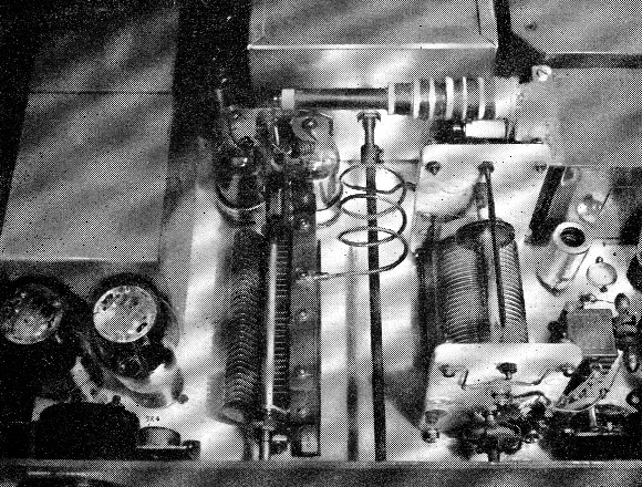
The Q in the plate circuit can be set with reasonable accuracy, since a variable inductor and a high-capacity variable condenser are used in a pi-network circuit. The condenser is a 190 pF-per-section dual, and the stators are connected together by a ½-inch-wide copper strap. Connected this y, the condenser measures 40 to 400 pF (including stray capacity to the chassis). It is a simple matter to plot the capacity vs. dial setting, since the condenser plates are semicircular and give straight-line-capacity tuning, and hence the tuning condenser can be set to any given capacity on any band. The circuit is then tuned to resonance by adjustments of the variable inductor, and load changes are made with the output condenser stack of S2. The Q chart of Fig. 6-9 in the 1953 Handbook (page 137) was used for working out these settings - the maximum value of d.c. plate current (227 mA) is used in the denominator.
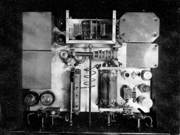
This top view of the linear amplifier shows the grid-tank shield removed. The power-supply components are on each side of the chassis - the two screen VR tubes can be seen to the left of the grid circuit.
Regulation of Power Supplies
In no other type of transmitter is the regulation of power supplies as important as in s.s.b. transmission. For a clean s.s.b. signal, the only factor governing the output signal should be the r.f. driving signal at the input. With the exceptign of Class A operation (used only at low power levels because of its relative inefficiency), the average plate and screen currents vary over wide ranges at a syllabic rate. If grid current is drawn during part of the operating cycle, as in AB2 and B operation, the grid current also varies. If these variable current demands affect the voltages of the power supplies, the effect is to add some plate or screen (or grid) modulation, or a combination of them to the output. These will generate new and undesired components, or distortion products, and they will degrade the over-all signal. It is therefore important to use well-regulated power supplies with a s.s.b. linear amplifier.
The requirement of a grid-bias supply well regulated over a wide current range is avoided by using 6146s, which draw a very low value of grid current on peaks, and by using a "stiff" bias supply. The bias voltage is adjustable and, in practice, there is no detectable voltage change, even on modulation peaks. The supply is "stiffened" by using a low-resistance voltage divider and a large electrolytic condenser across the output.
The screen supply is easy to regulate, since the maximum screen-current demand is less than the maximum current a VR tube will handle, and a VR-105 and VR-150 in series gives the necessary 255 volts. The dropping resistor to the VR tubes is adjusted so that, with no modulation, the VR tubes pass their maximum current of 40 mA.
Getting the best possible regulation from the average plate power supply is no easy task. There are many components that contribute to the IR drops; e.g., the transformer secondary, the rectifier tube (if high-vacuum), the input and smoothing chokes, and the a.c. line. To smooth out the syllabic variations, a large amount of output capacity is recommended, and too many microfarads at this point are not within the realm of possibility. One full-wave rectifier could have been used in the rig to be described, but two were used, to reduce the IR drop. Mercury-vapor tubes would be even better, perhaps, in this respect. Originally, one surplus plate transformer was used. There were no current ratings on the case, but the transformer looked big enough and felt heavy enough. Later, a duplicate transformer was acquired and connected in parallel. Immediately the regulation was improved, and the IR drop through transformer resistance was cut in half. Don't go right out and buy two similar transformers - the point is mentioned just to emphasize the need for conservatively-rated power-supply components when good regulation is your objective.It was always considered desirable to have two matched filter chokes, one swinging and the other smoothing. Yes, you read it right - it says "was." In s.s.b., only one is sufficient, and using only one cuts down another source of series resistance and poor regulation. With 24 pfd. of filter condenser and the swinging choke, the regulation is improved and the ripple is only 2% per cent.
Stability
Stabilization of any r.f. amplifier is important, of course, but it sometimes becomes more important in linear-amplifier work because of the high power sensitivity of the linear. Instabilities manifest themselves as fundamental oscillations or regeneration, and l.f. and v.h.f. parasitics. As a matter of precaution, v.h.f. parasitic suppression was built into this amplifier before any testing was done. It is reasonably safe to assume that there is everything to gain and nothing to lose by exercising this precaution with multigrid r.f. tubes, especially where they are operated in a high-power-sensitivity condition.
Oscillation or regeneration at the operating frequency is evidence of plate-to-grid feed-back and the amplifier was neutralized to offset any such coupling. As originally built, no neutralization was included, although every precaution was included to minimize feed-back, such as grounding all cathode pins with heavy wire and isolating the grid and plate circuits. The amplifier was stable, but after several days of band-hopping between 75 and 20 it was noticed that maximum output did not occur at the resonance dip indicated by the plate-current meter. Adding the Bruene grid-capacitance bridge neutralization circuit(2),(3) brought maximum output at the plate-current dip.
The introduction of this neutralization introduced another factor in the form of "birdies" across the band, similar to ITV. This was an unexpected l.f. oscillation that was eliminated by the addition of a 1000 ohm resistor across the grid r.f. choke. Another value of r.f. choke would probably have cured the trouble, but none was available at the time.
The amplifier circuit is shown in Fig. 1, and the power supply diagram is shown in Fig. 2. The thermal time delay, K1, was included to insure proper warm-up time for the 6X4 and 6146s.
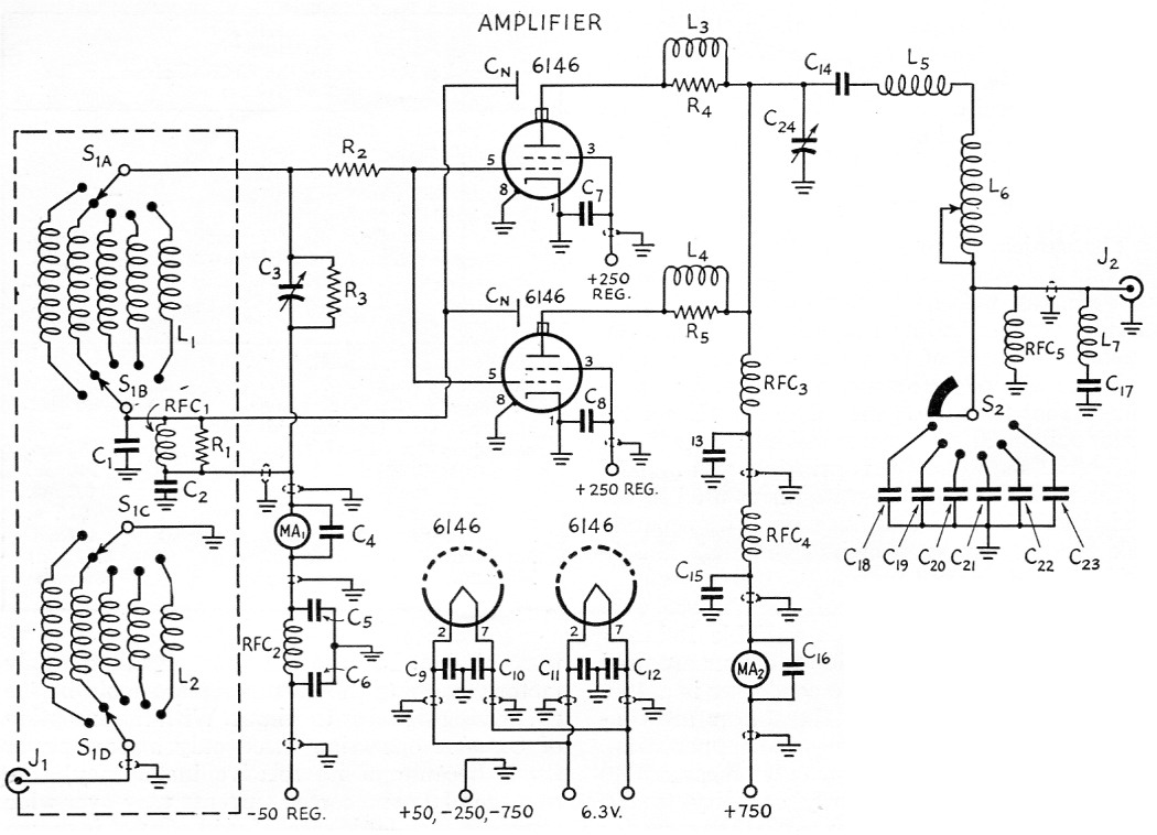
Fig. 1. Wiring diagram of the linear amplifier.
| C1 | 250 pF mica. |
| C2,C4-C12,C16 | 1 nF disk ceramic. |
| C3 | 250 pF variable (Hammarlund MC-250M). |
| C13 | 500 pF 10 kV ceramic (CRL TV3-5301). |
| C14 | 2 nF 2500 V mica. |
| C15 | 1 nF 2500 V mica. |
| C17,C18,C19 | 100 pF 2500 V mica. |
| C20,C21 | 200 pF 2500 V mica. |
| C22,C23 | 500 pF 2500 V mica. |
| C24 | 380 pF variable (Cardwell MO-180-BD, stators in parallel). |
| CN | Neutralizing condenser (see text). |
| R1 | 1000 Ω 2 W carbon. |
| R2,R4,R5 | 100 Ω 2 watt carbon. |
| R3 | 10 kΩ 10 W noninductive (Sprague Koolohm NIT). |
| L1,L2 | See coil table. |
| L3,L4 | 6 turns No. 20 tightly wound around R4 and R5. |
| L5 | 3½ turns No. 10, 2 inch diam., 3½ inches long. |
| L6 | Variable inductor (B & W 3852). |
| L7 | Series-resonated with C17 to TV channel most likely to be interfered with. |
| MA1 | 0 - 15 milliammeter. |
| MA2 | 0 - 500 milliammeter. |
| RFC1,RFC5 | 2.5 mH r.f. choke. |
| RFC2 | 7 µH r.f. choke (Ohmite Z50). |
| RFC3 | 225 µH r.f. choke (National R-175). |
| RFC4 | 4 µH r.f. choke (National R60). |
| S1 | 4 pole 5 position switch of L1L2 assembly. |
| S2 | Progressive shorting switch (Centralab P1S wafer and P-121 index). |
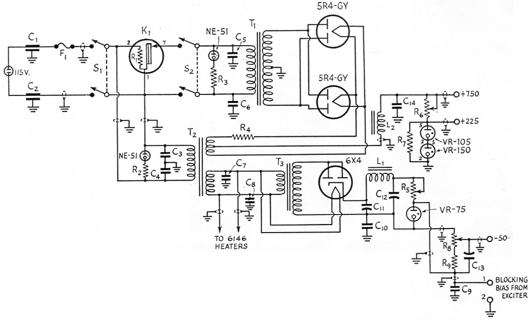
Fig. 2. Wiring diagram of the power supply.
| C1,C2 | 100nF feed-through capacitor (Sprague Hypass). |
| C3-C8 | 5 nF disk ceramic. |
| C9,C10 | 1 nF disk ceramic. |
| C11 | 10 µF 450 V electrolytic (see Cu). |
| C12 | 80 µF 450 V electrolytic (Mallory FP-245). |
| C13 | 80 µF 150 V electrolytic. |
| C14 | 24 µF total, 1000 V |
| R1 | Heater built in K1. |
| R2,R3 | 200 kΩ, 1 W |
| R4 | Homemade 0.35 Ω resistor. Can be omitted if T2 has 5 volt winding. |
| R5 | 1 kΩ, 10 W adjustable. |
| R6 | 20 kΩ, 50 W adjustable. |
| R7 | 100 kΩ, 2 W. |
| R8 | 2500 Ω 2 W potentiometer (Ohmite AB CU2521). |
| R9 | 2400 Ω, 2 W. |
| L1 | Small filter choke, not over 250 Ω resistance. |
| L2 | 5-20 H 300 mA swinging choke. |
| F1 | 5 A fuse. |
| K1 | Thermal time delay (Amperite 115N030 wired for 6 A). |
| S1,S2 | D.p.s.t. toggle. |
| T1 | Plate transformer, to deliver 750 V d.c. at 300 mA, approx. |
| T2 | Filament transformer, each secondary 6.3 volts at 4 A. |
| T3 | Filament transformer 6.3 V, 3 A filament transformer. |
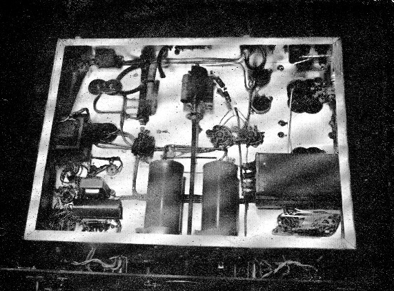
A close-up view of the r.f. section shows the neutralizing condenser mounted close to the two 6146 plate connectors.
Construction
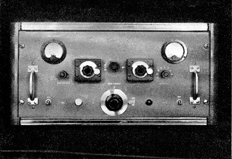
The panel and chassis are aluminum, with an 8¾ × 17 inch panel and a 13 × 17 × 3 inch chassis. The large chassis allows for mounting of many of the smaller components on the underside. The chassis is set back from the panel, to allow room for the mounting of parts between the panel and the front apron of the chassis. This spacing also serves to bring the rear apron, with its coax connectors and terminals, flush to the inside back of the cabinet.
All wiring was done with shielded wire where possible, with no attention being paid to its length. It is bonded and grounded to the chassis at all convenient points. Disk ceramic condensers are used liberally throughout, in keeping with present practice. The grid-tuning condenser is -mounted directly under the grid-turret shield box, permitting short lead lengths.
A series of ¾ inch holes is drilled directly above R6, the series bleeder, for better heat dissipation. A current of 40 mA flows through this resistor when the plate switch is "on."
Condenser C17 is mounted as close to the output coax connector, J2, as possible, and flush against the chassis. It is "grid-dipped" with L7 to the frequency of the TV channel most likely to be interfered with. J2 is shorted during the grid-dipping process.
The "C" bias dual filter condenser, C11C12 is mounted on an insulating wafer because the can is negative and does not ground to chassis. A disk ceramic condenser, C10, is used to by-pass the can to the chassis.
Type 4 mica condensers are used in the pi-network output stack because they lend themselves to firm mechanical mounting. Their voltage rating is higher than required for the power used, but they were on hand. The "safety choke," RFC5, is mounted across the condenser stack.
Both sides of the plate-tuning stators are connected together with %-inch-wide copper strap to reduce lead inductance and make use of the condenser's maximum capacitance. The self-resonance of this condenser, C24, connected this way, measures 120 Mc. - well outside any TV band.
The 24 µF of filter condenser in the plate power supply is mounted under the chassis - it consists of the two center cylinders plus the two condensers on the right-hand side. Shielded wires and disk ceramics are liberally used throughout the unit.
The plate choke, RFC3, is mounted horizontally, to bring the " hot end" directly centered over the plate caps of the 6146s. Here, too, Minch copper strap is used to connect the end of the choke to the plate blocking condenser, G14, resulting in short leads and low inductance. This choke works as well on the 15-meter band as it does on 10, when we used the grid-dipper as the source of excitation for preliminary tests. This may be due to the proximity of the adjacent components adding sufficient capacitance to move the expected "hole" out of the 15-meter band.
Parts R1, RFC1, and C1 are mounted just inside the input turret shield can, and directly in back of the 6146s. A lead is brought through close to the bottom of the vertical side of the shield can, by means of a feed-through insulator. This lead connects to the vertical part of the neutralizing condenser, CN. The neutralizing condenser is made of a thin aluminum sheet cut in the shape of the letter "T", with the horizontal part of the T 1 inch high and 4 inches wide. It is mounted on a ceramic post so that it can be bent away from the plates of the 6146s.
Tuning and loading
Tuning is straightforward as with any amplifier of similar design. However, careful attention should be paid to loading.
Light loading cannot be tolerated because (a) the screen dissipation may be exceeded. (An indication of this can be seen by the screen VR tubes being extinguished. When the amplifier is properly loaded, these VR tubes should not "go out" during any part of the modulation cycle). (b) "Flattening" of the peaks will occur before rated output is reached, assuming proper drive requirements are met. If reduced power output is wanted, just turning down the speech level control will do the trick. There is a point of loading where maximum rated output occurs without flattening, and loading beyond this point serves only to reduce the efficiency and output.
Details of loading and testing are beyond the scope of this article. Readers are referred to the excellent text, "How to test and align a linear amplifier," May, 1952, QST.
A word about tuning. As with any r.f. device that covers a wide band of frequencies, caution must be exercised to be sure that only the desired output frequency is amplified. This is especially advisable when using beam or tetrode tubes, because of their high power sensitivity.
With the grid circuit tuned to resonance at the fundamental, the plate circuit should be tuned starting with the maximum number of turns in the variable inductor. The first resonant point is the desired frequency.
Results
This linear has been on the air regularly on 20 and 75 meters up to the time of this writing. It has been dummy-load tested on the other bands. Stable as the Rock of Gibraltar, all reports indicate that it transmits a high-quality signal with excellent sideband suppression, and a minimum of distortion products. This result was the hoped-for goal when the unit was in the design stage. That it is so is due to the application of good design practices for s.s.b. transmission.
It is affectionately called "Little Firecracker"; for its small size, it sure gives a loud report.
A word about TVI - this is the first transmitter in use at this station to prove itself completely TVI-proof. With this unit operating, the family, watching any one of the seven local TV stations, was completely unaware of its being in use. Furthermore, at the time, the linear was out of its cabinet and no low-pass filter was used.
For his patient efforts photographing the "Little Firecracker," special thanks to Henry Marcus, W2AJX.
Notes
- Ehrlich, "How to test and align a linear amplifier," QST. May. 1952.
- Grammer, "Pi-network tank circuits for high power," QST, Oct., 1952.
- Bruene, "How to neutralize your single-ended tetrode final," CQ, Aug., 1950.
Ben Russ, W2QZ.