"De Luxe" keying without relays
An improved keyed-amplifier break-in system.
Here is a keying system that should enjoy widespread popularity. It permits amplifier keying (generally acknowledged to be the only truly chirp-free method) to be combined with excellent break-in operation, without the use of relays. If you have ever paid the slightest bit of attention to the keying characteristics of your rig, this is "must" reading for you.
There seems to be no question that grid-block keying allows the easiest and most effective control of a transmitter's keying characteristics. However, when it is desired to key the oscillator simultaneously, so that break-in may be used, difficulties arise. These difficulties are usually resolved by the use of a relay, as shown on page 239 of the 1953 Handbook.(1) The author has never found relays very satisfactory for this purpose. Noise, slow action and contact bounce are usually present in the best available relays. The following circuit was therefore developed to allow both grid-block and oscillator keying at the same time, without relays. The grid-block keying is applied to a keyer tube in the cathode circuit of an r.f. amplifier stage.
The basic method of operation is as described in the Handbook article. When the key is closed, the oscillator starts very quickly, and the resultant click is gone by the time the grid block keyed stages passes any appreciable signal. When the key is opened, the inverse action takes place, with the oscillator staying on until the grid-blocked stage is turned off.
The basic circuit is shown in Fig. 1. R1, R2, C1 and the 6BL7 comprise a standard vacuum tube keying circuit. The oscillator is a series-tuned Colpitts, using a 6CL6, with the variation from the conventional circuit that the grid leak, Rs, is not returned directly to ground. The unusual section of the circuit is the 12AU7 control tube, which turns the oscillator on and off by changing the bias applied to the oscillator grid. This section may be described as a grounded-grid amplifier stage with a cathode-follower input, driven far into the nonlinear region. This is a case where nonlinear operation of an amplifier is absolutely necessary for correct functioning of the circuit. Also, the term "amplifier" may be misleading, as the "output" swing is considerably less than the "input" swing.
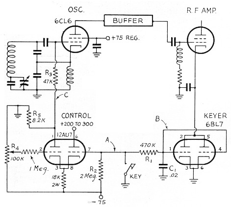
Fig. 1. Circuit diagram of the break-in keying circuit.
The operation of the circuit is as follows: Initially, after the key has been open for a considerable period of time, point B will be at -75 volts, cutting the 6BL7 keyer tube off. Also, only a very small current flows in the right half of the 12AU7 control tube because of the large value of cathode resistance. The bias on the left half of the 12AU7 is adjusted by R4 so that a sufficiently large negative potential appears at point C to cut the oscillator off.
When the key is closed, point A immediately goes to ground potential, and the cathodes of the 12AU7 control tube will be pulled to about +5 volts by the cathode follower action of the right half. This puts the grid of the left half at a large negative potential, so the left-hand section will be cut off, and its plate potential will go to ground. This will remove the negative bias from the oscillator grid, and allow the oscillations to start. All of the above actions happen very quickly, so that the oscillator click will be over by the time the 6BL7 keyer allows much signal through the keyed stage. (Point C does not actually go to ground potential because the oscillator grid current flows through R5.)
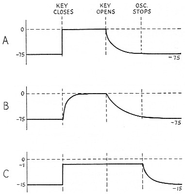
Fig. 2 -Voltage waveforms corresponding to points A, B and C in Fig. 1. The keyed output characteristic corresponds closely to B.
When the key is opened, points A and B will have approximately the same potential, and will start falling toward -75 volts in an exponential fashion, cutting off the 6BL7. At some time after the 6BL7 is pretty well cut off, the voltage will have fallen far enough that the left half of the 12AU7 will start conducting, biasing the oscillator grid negative and stopping the oscillations. The oscillator will have a chirp when it turns off, but it will not appear in the output of the transmitter.
The adjustment of the circuit is quite simple. The 12AU7 control tube is removed from its socket, and the grid-block keying adjusted to the desired characteristics.(2) R4 is then placed at its negative end, and the 12AU7 replaced and allowed to warm up. R4 is then advanced toward its positive end until the voltage at point C is about -15 volts. The farther that R4 is advanced, the quicker the oscillator will turn off after the key is opened. However, if it is advanced too far, the break keying characteristic may be clipped by the oscillator's turning off too soon. The setting of R4 should have no noticeable effect on the make keying characteristic.
For the 6BL7 keyer tube, the -75 volts bias should be adequate for amplifier plate potentials up to about 600 volts. If both halves are used in parallel as shown, it may be regarded as about a 1000-ohm cathode resistor. The tube's total current should be limited to about 100 milliamperes.
The circuit as shown gives no receiver protection or muting. These are both usually necessary if very much power is used. It is hoped to present a companion unit at a later date that will accomplish these functions.
Notes
- Also, Goodman, "Improved break-in keying," QST, March, 1948.
- With a fixed value of C1, the value of R1 controls the "make" characteristic, and the value of R2 controls the "break." Increasing resistance softens the keying. -En.
T.H. Puckett, W2JXM.