The tin can low-pass
An inexpensive filter for the novice.
The accepted correction for TVI troubles where the transmitter is at fault is to "bottle up" the transmitter in a shield and couple out through a low-pass filter. In this article, W1ICP shows how simple and inexpensive it is to build a low-pass filter that will handle the output of a 75-or 100-watt transmitter from 80 through 15 meters.
In traveling around the country, giving talks on TVI, the writer was rather surprised to find that many amateurs, particularly newcomers, shied away from building their own low-pass filters because they felt the task was beyond their technical ability. Actually, a low-pass filter is one of the easiest construction jobs that an amateur is likely to encounter. In addition, one can usually save considerably on the green stuff by building his own. The unit described in this article was built at a cost of less than fifty cents.
Before getting into a description of the actual construction of the filter, a few words are in order to explain what a low-pass filter is and what it will do. As we know from studying the questions in the License Manual for the Novice and General Class examinations, we don't want to radiate any spurious signals from our transmitters. When these spurious signals are harmonics or parasitic oscillations that fall in the television channels they can cause TVI plus the consequent headaches involved with maintaining good neighbor relations. Our problem is then one of keeping these harmonics from radiating. This is where a low-pass filter does yeoman duty.
A low-pass filter is a coil-condenser combination that, when properly installed on a transmitter, will pass all signals lower than its designed "cut-off frequency" while attenuating all other signals. In other words, let's assume we have a transmitter operating in the 80-, 40-, and 15-meter Novice bands. We want the signal from the band being used to go from the transmitter to the antenna and be radiated. However, we don't want harmonics or spurious signals higher than 21 Mc. to reach the antenna or the feedline. The answer is to install a low-pass filter at the transmitter output that will pass the 80-, 40-, and 15-meter signals while attenuating all higher frequencies. The filter shown in the photograph and at Fig. 1 is just such a device.
Construction
The box shown in the photograph was made from metal taken from two No. 2 tomato cans. This metal is an excellent material for making a small radio chassis or shield can. It is easy to bend and form small boxes from the metal found in "tin can" food containers. This metal is thin, and holes (for mounting tie points, etc.) can be punched out with a nail or ice pick. Also, the tin coating on the metal takes solder very easily. For construction, all one needs is a pair of tin snips, a soldering iron, and a supply of tin cans.
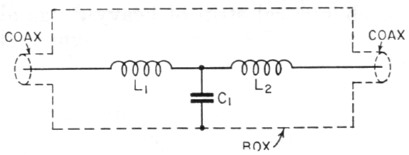
Fig. 1. Circuit diagram of the low-pass filter.
C1 - 220 pF, mica, 5 %.
L1,L2 - See text.
The dimensions of the box for the filter are 1¾ × 1¾ × 4 inches. Four pieces of metal are needed; one piece for the bottom and sides, 5¼ × 4 inches; two end pieces, 2¼ × 2¼ inches; and the top, 2½ × 4½ inches. The 5¼ inch length of the large piece is scribed off into three 1¾ inch sections. If a vise is available the piece of metal is clamped between two pieces of wood and then bent to form one side of the box. A metal straightedge or another piece of wood can be used to bend the tin to form a right angle. The piece is then clamped so that the remaining side can be bent. If a vise isn't available, a satisfactory job can be obtained by holding the piece of tin firmly between two boards and then pressing the metal against a flat surface until a right angle is formed.
The ends of the box are made up with a ¼ inch lip so that there will be plenty of soldering surface available when the ends are attached to the box. The top is made with a ¼ inch lip for the same reason. When soldering the ends to the box, be sure the iron is hot enough to insure good connections.
A ¼ inch hole is drilled or punched in the center of each end of the box to accommodate the coax leads to and from the filter. To avoid bending the box out of shape, a small block of wood should be held against the other side of the piece being drilled. Three tie points are needed to hold the coils and the condenser in place. The tie points used in the installation shown here are the single-terminal bakelite strip type selling for about three cents each. Three holes are needed on one side of the box to accommodate the 6-32 screws for holding the tie points.(1) The placement of the holes will depend on the type of tie point used, but in any case, they should be placed so that the coils, L1 and L2, will be spaced about one inch apart and centered in the box. Remember to hold a piece of wood under the side of the box being drilled to avoid bending the metal.
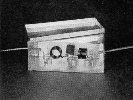
View of the filter showing how the coils are mounted on the tie points. The condenser, C1, is visible behind the center tie point.
The coils are made of No. 16 enamel-covered wire. Each coil is 7 turns, ½ inch inside diameter and ½ inch long. Any solid ½ inch diameter object, such as a drill bit shank, wooden dowel rod, etc., can be used as a winding form. Be sure to leave an inch or so lead length at the coil ends for mounting on the tie points.
Wiring
As can be seen in the photograph, the coils are mounted at right angles to each other to avoid undesired coupling. Before mounting the coils on the tie points, be sure to scrape the enamel from the wire where it is to be soldered. (Many beginners find themselves in trouble here because they don't know that paint or enamel covering should be removed from wire before one can solder to it!)
One lead of the condenser, C1, is soldered to the bottom of the box directly below the center tie point. The other condenser lead is connected to the center tie point along with two coil leads. Keep the condenser leads short; about ¼ inch will suffice.
The two end tie points serve as a junction point for the coil ends and the coaxial cable inner conductors. Many amateurs use coaxial cable, commonly referred to as "coax," for connecting the filter to the transmitter and the antenna or antenna coupler. There are four types of coax commonly used by amateurs: RG-8/U, RG-11/U, RG-58/U, and RG-59/U. Any of these types will work with the filter. The coax used in the filter shown is RG-59/U because it is cheaper and easy to handle. However, the filter is not designed to work with 300-ohm Twin-Lead, or for that matter, any balanced line. This doesn't mean that you can't use Twin-Lead to feed your antenna and still use a low-pass filter. When we discuss the filter installation we'll show you how to use Twin-Lead if you wish.
To connect the coax to the ends of the coils, the following procedure is followed: About two inches of the vinyl covering is removed from one end of the coax, then the outer conductor braid is trimmed back to a point about inch from the vinyl covering. Enough of the covering around the inner conductor is removed to permit a connection to the tie point. The end of the cable is then fed through the hole in the end of the filter box up to the point where the vinyl covering begins. The ½ inch of outer conductor braid is then spread out around the hole and soldered in place. Do this carefully, as too much heat will melt the covering of the inner conductor, causing a shorted cable.
The same procedure is followed at the other end of the filter. Coax fittings can be installed on either end of the filter, but they, of course, add to the cost of the unit.
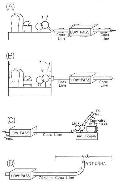
Fig. 2. At (A) we see the wrong way to connect a filter and coaxial line to a transmitter. The harmonics flow over the outside of the cable, over the filter, to the antenna, and can be radiated. At (B) the harmonic energy is confined inside the transmitter and can only flow through the cable and inside the filter.
At (C) and (D) we see two methods of connecting the low-pass filter to the antenna system.
Installation
For a filter to work properly, the radio signal should flow through the circuit, not around it. In other words, if we want the filter to attenuate harmonics, we must keep the harmonics inside the coax and inside the filter box. This means the filter must be attached to the transmitter properly. This is shown at Fig. 2. At (A), the wrong way to install the filter, the coax is connected to the link on the final amplifier of the transmitter with no shielding being used on the rig. The harmonics, indicated by arrows, radiate from the transmitter and flow on the outside of the coax line and over and around the filter to the antenna. In this case, the filter doesn't help the situation in the slightest. However, at (B) the harmonics are confined inside the transmitter and they must flow through the coax to the filter. In this way they are attenuated and never get a chance to reach the antenna. You will notice that, in this case, the coax is connected to the back panel of the transmitter, making a good tight connection. This is usually done by installing a male coax connector, 83-1SP, on the coax cable coming from the filter, and a female connector, 83-1R, on the transmitter. When mounting the socket on the transmitter, be sure to clean any paint from around the mounting point. Incidentally, the filter can be inserted in the coax line in either direction; in other words, the input and output characteristics of a filter are the same.
Coupling to the antenna
In the average station the coax lines between the transmitter and filter and between the filter and antenna coupler (if one is used as described below) probably will be quite short. It is preferable to use the minimum possible length between the transmitter and filter; the other length is not so important because there will be very little harmonic energy in the line on the "output" side of the filter. If the length to the antenna coupler is not more than a few feet the coupler can be tuned in just the same way as before installing the filter, although the settings may differ. Longer lines may require "matching," a subject that is beyond the scope of this article but which is covered in the Handbook.
There are two generally used methods for connecting a filter to the antenna system. The first is to connect the output of the low-pass to an antenna coupler as shown at Fig. 2C. In this case, the coax is connected to the link on the antenna coupler, and the coupler is used to couple the antenna to the link. This system has the advantage of offering additional harmonic attenuation because of the additional circuit tuned to the output frequency. Also, the feedline to the antenna can be 300-ohm Twin-Lead, open-wire line, or for that matter, practically any type of transmission line.
At Fig. 2D, we find the low-pass filter connected directly to a half-wave antenna via a 75-ohm coax line. A half-wave antenna offers a pretty good match for 75-ohm line, and this system will work well for those amateurs using such an antenna.
If greater harmonic attenuation is needed, it is suggested the reader study the BCI-TVI chapter of The Radio Amateur's Handbook. Several filters are described there that will furnish considerably more attenuation than the "Tin Can." However, for most Novice installations, the filter described here will be more than adequate.
Notes
Lewis G. McCoy, W1ICP.