An r.f. assembly for mobile or fixed-station work
Here is a rugged r.f. unit that fulfills most of the mobile fan's needs. Compactness; rapid band-changing without plug-in coils, complicated tracking or involved r.f. switching; a minimum of tuning controls; and full consideration of the ever-present mobile power-supply problem are several features which make this unit a mobile-man's all-purpose rig. And, of course, there is nothing to prevent using the transmitter for fixed-station or portable-emergency use operating the 6146 final at full rated input.
Ganged multiple-circuit tuners in a six-band rig.
Although many home constructors lay honest claim to a strong anticommercial attitude toward transmitting gear, it must be admitted that more than one sometimes cast admiring eyes at the neat mobile packages available on the market. Most manufactured units certainly have eye appeal, and a compactness that is difficult to duplicate in the home workshop. The ability to produce rigs of such small dimensions is not difficult to understand if one examines the interior of one of these units. Here one will find many special fittings and components of miniature size that are not available to the average ham. However, the ham who likes to roll his own may not be too concerned about saving the last cubic inch of space if he gets the sort of performance and convenience he wants.
The mobile transmitter shown in the photographs represents a practical compromise between commercial standards of compactness and those which can conveniently be met in the home workshop by a ham with average skill in construction. Its chief attributes are as follows:
- No power output has been sacrificed for the sake of miniaturized construction, yet it is compact enough to fit in a convenient spot under the instrument panel.
- Six-band coverage is accomplished employing neither plug-in coils nor complicated r.f. switching. The only r.f. switch is a simple one that selects one of two output links. Band-changing, in some instances, requires the readjustment of only a single control.
- Through the use of ganged condensers, only two circuit-resonating controls are needed.
- Construction is straightforward and does not require the use of special components or hardware that is difficult to make.
- The transmitter will work satisfactorily from almost any practical mobile power supply.
- The unit can easily be removed from the car to the home-station operating table, and be operated with the final running at full rated input - 90 watts c.w. (or 65 watts 'phone with a suitable modulator).
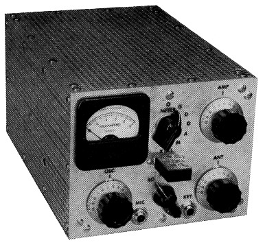
Front view of the 6-band mobile transmitter. The control knob for S2 is located between the meter and the dial for C3 and C4. S1 is directly below the crystal socket, with the knobs for C2 and C6 to the left and right, respectively. J1 and J2 are at the bottom of the 4_7/8 × 6¼ inch panel. The perforated aluminum cover is 9_1/16 inches deep and has a hole punched in the left side to permit adjustment of C1.
There were reasons why it was believed not entirely desirable to include the modulator in the r.f. unit. In the first place, of course, space under the dash is usually at a premium, so the dimensions of a unit intended primarily for mounting in this location should be minimum. There is negligible disadvantage in placing a separate modulator unit where more space is available. Another point is that it is practically impossible to design an audio section that will work satisfactorily and economically over a wide range of plate voltages and power-output levels. It is preferable that the design of the modulator be based on the available power supply.
The circuit
The circuit of the transmitter, Fig. 1, shows an r.f. line-up consisting of a grid-plate crystal oscillator followed by a multiplier-driver stage and a 6146 power amplifier. The oscillator employs a 5763 tube, V1, uses 3.5, 6, or 7 Mc. crystals, depending on the output frequency desired, and has a parallel-feed plate circuit tuned by C2 and L1. This stage ordinarily is operated at the crystal frequency, but it can also be tuned as a frequency multiplier to the second harmonic of 3.5 Mc. crystals if such operation becomes desirable. Feed-back can be adjusted by C1 to suit crystals of varied activity. Cathode bias protects the tube in the event of crystal failure. Output from the oscillator is capacity-coupled to the grid of V2.
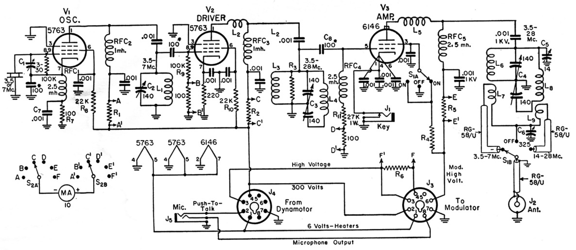
Fig. 1. Wiring diagram of the six-band mobile transmitter.
| C1 | 3-30 pF trimmer. |
| C2 | 140 pF variable (Hammarlund MC-140-S). |
| C3,C4 | 140 pF per section variable (Hammarlund MCD-140-M). (Ganged to single control.) |
| C5 | 14 pF midget variable (Johnson 15M11). |
| C6 | 325 pF variable (Hammarlund MC-325-M). |
| R1,R2 | 5 times meter shunt: 60 inches No. 34 enam., scramble-wound on 1 megohm, ½ watt resistor. |
| R3 | See text. |
| R5,R6 | 25 times meter shunt: three 32½ inch lengths No. 34 enam., connected in parallel and scramble-wound on 1-megobm, ½ watt resistor. |
| L1 | 11 µH: 43 turns No. 24, 1_5/16 inches long, 5/8 inch diam. (B & W 3008). |
| L2 | Parasitic choke: 4 turns No. 16, ¼ inch diam., turns spaced wire diam. |
| L3 | 6 µH: 20 turns No. 24, 5/8 inch long, ¾ inch diam. (B & W 3007). |
| L4 | 2.85 µH: 21 turns No. 20, 1_5/16 inches long, 5/8 inch diam. (B & W 3007). |
| L5 | Parasitic choke: 6 turns No. 16, ¼ inch diam., turns spaced wire diam. |
| L6 | 6 µH: 20 turns No. 20, 1¼ inches long, 1 inch diam. (B & W 3015). |
| L7 | 5.2 µH: 18½ turns No. 24, 9/16 inch long, ¾ inch diam. (B & W 3012). |
| L8 | 2.85 µH: 16½ turns No. 20, 1 inch long, ¾ inch diam. (B & W 3011). |
| L9 | 0.4 µH: 4 turns No. 20, ¼ inch long, ¾ inch diam. (B & W 3011). |
| J1 | Midget closed-circuit jack. |
| J2 | Coaxial-cable connector (Amphenol 83-1R). |
| J3 | 8 prong female connector (Amphenol 78-S8). |
| J4 | 8 prong male connector (Amphenol 86-CP8). |
| J5 | Midget 2-circuit microphone jack. |
| MA | 0-10 mA d.c. meter (Simpson Model 127). |
| S1A | 1 pole 6 position (3 used) selector switch (Centralab PA-1). |
| S1B | 1 pole 11 position (3 used) selector switch (Centralab PA-11). |
| S2 | 2 pole 6 position selector switch (Centralab PA-2003 or PA-3 section on PA-300 index). |
NOTE: See text for additional data on L8 and L9.
NOTE: S1A and S1B mounted on Centralab PA-300 index assembly.
Unless otherwise specified, all resistors are ½1 watt, and all fixed capacitors are disk ceramic.
* Indicates a mica capacitor.
While it might be possible to cover all six bands with the oscillator and final alone, a multiplier stage is included. This not only permits the final to be used as a straight amplifier on all bands, but it makes it unnecessary to push the oscillator to the limit to secure adequate drive. As it is, the two exciter tubes loaf along at a total plate current of about 18 mA.
The multiplier stage also employs a 5763, V2, uses parallel plate feed, and is tuned to resonance by a 6-band tuner consisting of C3, and inductors L3 and L4.1 Cathode bias is used in this stage not only to protect the tube, but also to limit the input to only that necessary for adequate drive to the final. Plate current is approximately 10 ma. L2 is used to suppress v.h.f. parasitic oscillation.
A resistor, R3, connected across L3 of the tuner, serves three useful purposes. First, it helps to level off the drive to the final amplifier. In particular, it reduces the output of the driver at the lower frequencies where there is otherwise an overabundance of drive. Its effect on drive at the higher frequencies is relatively small. Second, it effectively broadens the response of the tuner at the lower frequencies, thus simplifying the problem of tracking this circuit with the one in the final. And last, but by no means least, the addition of R3 is an important aid in stabilizing both driver and final at the lower frequencies where all three stages may be operating at the same frequency.A 6146 was selected for the amplifier, principally because it is one of the few tubes that works well over a wide range of plate voltages. It will perform just about as efficiently at low voltages as it does at its maximum rating. Thus, the input can be adjusted to suit the available power supply and modulator. Parallel plate feed is used in this stage, too, and the output circuit is resonated with a multiband tuner, C4-L6-L8, similar to the one in the driver stage with which it is ganged to a single control. C5 is a trimmer to aid in the tracking adjustment. L6 is a v.h.f. parasitic choke. A keying jack, Jl, is provided for those who may want to work c.w., either mobile or at a fixed station. Su in the screen circuit holds the input to a safe value (almost zero plate current at 450 volts) during periods of tune-up or testing.
Two link coils, L7 and L9, are required to provide proper output coupling. L7 is used for output at 3.5 or 7 Mc., while L9 takes care of the remaining bands. The proper link coil is selected by S1B. Although, for the sake of clarity, this switch is shown as a simple selector switch, actually, the one specified in the parts list is one that not only disconnects the unused coil, but short-circuits it as well. The link circuit is tunable by means of C6i and this provides a means of adjusting the loading on the final. This output circuit is designed to feed into 50 ohm coax cable.
Power and Metering Circuits
A 10 mA meter can be switched by S2 to check the plate current of each stage, or the grid current of each of the last two stages. R1 and R2 multiply the meter reading by 5 to give a full-scale reading of 50 ma. Similarly, R6 and Rs multiply the reading by 25 for a full-scale reading of 250 ma. The values specified for the shunts will hold only for the meter specified, or one of the same internal resistance.
Two connectors, J3 and J4, are provided at the rear of the chassis. J3 takes a cable from the modulator unit, while J4 is for a cable from the power-supply unit. On 13, the speech input terminals of the modulator unit should be connected across Pins 7 and 8. The secondary of the modulation transformer should be connected across Pins 3 and 6. The hot side of the audio filaments should be connected to Pin 1, and the high-voltage input terminal of the modulator to Pin 4. With the latter connection, the meter will read modulator plate current when the meter switch is in the F position.
In this bottom view of the mobile transmitter, C2 and C6 are to the left and the right, respectively, of S1. S1A is the section closest to the panel. L1 (mounted on a ½ inch cone insulator), C1 and RFC2 form a triangle to the rear of C2. The plate-circuit feed-through, RFC8, and the tube socket - all for V2 - are to the rear of S1B. L6 and L7 are mounted parallel with the rear of the chassis and the L8-L9 assembly is supported by feed-through insulators above and to the left of L6. J2, J3 and J4 are mounted on an aluminum bracket shown at the bottom of the photograph.
For the plug that fits into J4, the winding of the push-to-talk relay should be connected across Pins 1 and 2. The positive high-voltage lead from the power unit should connect to Pin 3, and the hot side of the car battery should connect at Pin 1. If the power supply delivers 300 volts or leas, Pins 3 and 4 should be connected together. If the power supply delivers appreciably more than 300 volts, a series-dropping resistor, of suitable value to bring the voltage at Pin 4 down to 300 volts, should be connected between Pins 3 and 4, instead of the short.
Construction
Three types of aluminum - plain sheet, perforated sheet, and angle stock - are used in the construction of the transmitter.(2) The specifications for the material used are as follows:
Alcoa 2SH-14 aluminum sheet, 0.064 inch thick:
- Panel - 4_7/8 by 6¼ inches
- Chassis plate - 5_31/32 by 9 inches
- Partition (see top view) - 5_31/32 by 3 inches
- Rear connector bracket (see bottom view) 6¾ by 2 inches
Perforated aluminum sheet for cover, 0.051 inch thick:
- 2 pcs. (top and bottom) - 6¼ by 9_1/16 inches
- 2 pcs. (sides) - 4¾ by 9_1/16 inches
- 1 pc. (rear) - 4¾ by 6_1/8 inches
Angle stock:
- Approximately 7½ feet, ½ by ½ by 1/16 inch
The photographs show how the chassis and panel have been constructed as a unit that slides into the perforated cover. A layout of the panel is shown in Fig. 2. A rear-view plan is shown so that the constructor may make markings directly on the metal without disfiguring the front surface.
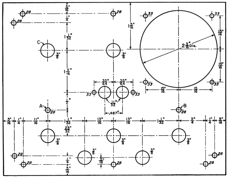
Fig. 2. Layout drawing of the panel (rear view) for the six-band mobile transmitter.
Lengths of angle stock, drilled and tapped to accommodate machine screws, are fastened along the four edges of the panel, on the inside. The strips of angle must be set in from the edges of the panel by the thickness of the cover material. The angles are fastened to the back of the panel by 6-32 screws in the No. 28 holes skirting the edges of the panel. The two pieces that meet at the upper right-hand corner (Fig. 2) must be filed out to clear the round case of the meter. They must also be drilled to clear the No. 4 screws used to mount the instrument.
Holes marked A and B are used for fastening a 5_1/8 inch length of angle across the back of the panel to serve as a support for the front edge of the chassis plate. The holes in the angle should be located so that the top surface of the chassis plate will be inches up from the bottom edge of the panel. The chassis plate must be notched so that its front edge will fit flush against the back of the panel.
Before attaching anything permanently to the chassis or panel, the partition on which the 6146 is mounted should be made. The partition is made from the 5_31/32 × 3 inch piece of aluminum. Bend a 3/8 inch mounting lip along the bottom edge, and then clip or round off the two top corners to clear the cover when it is slipped on.
Now fasten the chassis-supporting angle to the panel. Slip the front edge of the chassis plate over the angle, and hold it there while you slide the partition up against the back of the panel, keeping the bottom lip of the partition tight against the chassis. Then, using the panel as a template, scribe a hole in the partition that matches hole C (Fig. 2) in the panel. This will guarantee that the shaft hole in the panel and the one in the partition will line up accurately.
Notch out the mounting lip of the partition to clear the ceramic base of the rear tuning condenser when the latter is mounted.
The 6146 socket is centered on the partition with its mounting holes in a vertical line, and the grid terminal to the left as viewed from the rear of the partition. The socket is mounted on %-inch tubular spacers. A A-inch clearance hole should be drilled in the partition opposite the grid terminal. Considerable time will be saved if the disk ceramics and leads connecting to the socket are attached and soldered before the socket is mounted permanently.
The partition is placed 434 inches from the panel, and another A-inch hole, lined with a rubber grommet, is drilled in the chassis, directly below the socket, to pass filament, cathode, and screen leads.
The bracket that supports J2, J3 and J4 (see bottom view) should now be fabricated. Use the 2 × 6¾ inch piece of aluminum. The bracket has a 3/8 inch mounting lip bent up along one side, and ¾ inch braces bent up at the ends. A neater job will result if the ends of these braces are cut diagonally. The finished height of the bracket should be 1_5/8 inches. Placement of connectors on the bracket is not especially critical, and can be estimated from the bottom view. When the bracket is finally mounted, it is held in place by machine screws that pass through the chassis and then thread into a 5 inch length of angle centered along the edge, on the opposite face of the chassis plate.
The remainder of the layout work can be done most easily by the following procedure: Temporarily mount the panel components, and the partition, with the 6146 inserted in its socket, and the amplifier tank capacitor, C4, in place. Scribe lines on the chassis, along the inner edges of the ceramic bases of C3 and C4, across the rear of C4, and mark hole centers directly under the inside stator terminals of the condenser C4. The latter will indicate the positions of the feed-through insulators that support L8 and L9 (see bottom view). Now make marks on the chassis indicating the rearmost edges of all panel-mounted parts, and also draw a line across the chassis, holding the scriber against the front of the partition.
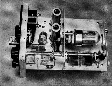
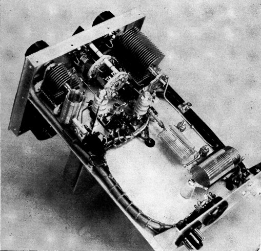
As seen in this top view of the mobile transmitter, V1 is located to the right of the milliammeter, just above V2. L3 is mounted on a 1 inch cone insulator to the right of S2, and L4 is supported by the stator terminals of C3. C8, R11 and RFC4 are grouped to the lower right of a feed-through insulator used for the plate lead of V2. The 6146 is mounted on the right side of the aluminum partition, and L5, C4, C5 and RFC5 are in line below the tube. A metal coupling connects the shafts of the two multiband-tuner condensers in the foreground. R3 can be seen shunting the rear section of C3.
All components may now be removed from the chassis so that the positions of the tube sockets, r.f. chokes and other small components may be marked. The socket for V1 is centered 3_7/16 inches back from the panel and ¾ inch from the side of the chassis. V2 is centered 1¾ inches below V1 (top view). Pins 4 and 5 of each socket should face toward the rear of the chassis.
A study of the photographs should clearly designate the positions of the components still to be mounted. In addition to the feed-through insulators for L8-L9, and the plate lead of V2, another must be provided for the lead between the crystal socket and V1. Also, holes lined with rubber grommets should be provided in the chassis for the leads that connect to S2, RFC4, and RFC6.
Additional reminders that may be helpful are: L1 and L3 are fastened to their respective cone-insulator supports with Duco cement. Allow the cement to dry overnight before mounting these units.
A lug soldered to the last turn (plate end) of L6, and then mounted on a ½ inch cone insulator, provides support for this coil. The cold end of L7 is supported in a similar manner.
No. 12 tinned wire is used to support the plate end of L8, and the C6 ends of both L7 and L9.
The L8-L9 assembly is made from a single length of B & W Miniductor. Use a 20½-turn length of Type 3011, and break the winding at 4 turns from one end, leaving the support bars intact. After heavy leads have been soldered to the four free ends of the assembly, mount and then wire as shown in Fig. 1.
The shafts of C3 and C4 are ganged with a metal coupler (Millen Type 39003).
C6 is mounted on a bracket, 1 inch high, with a ½ inch lip, made from a 5/8 inch strip of aluminum.
For operation with a plate supply delivering between 300 and 450 volts, a 20,000 ohm 2 watt screen-dropping resistor (R4) works well. This value of resistance, with the appropriate wattage rating, can be most conveniently provided by mounting a pair of 10,000 ohm 1-watt resistors in series on the terminals of S1A.
R3 is a pair of 12,000-ohm 1-watt resistors connected in parallel and soldered between rotor and stator terminals of the section of C3 that connects to C8.
A four-terminal tie-point strip to the rear of V1 and V2 connects to the B+ ends of R8, R10 and RFC2, and to the meter side of R9. A single-terminal strip provides a junction point for C7, R7 and the oscillator cathode choke.
The five sections of the cover are held together by machine screws. These screws pass through the perforated aluminum and then thread into the lengths of angle that run along all closed edges of the cover. A cutout measuring 1% by 5M inches is made in the rear wall to provide clearance for the power and antenna connectors and their cables.
Adjustment
If it is not convenient to use the mobile supply for initial testing of the transmitter, any a.c: operated supply delivering between 300 and 450 volts at about 150 ma. may be used. If the voltage is higher than 300, it should be fed into Terminal 3 of J4, and a dropping resistor connected between Terminals 3 and 4. This resistor should have a value of 50 ohms for each volt that the power supply delivers above 300 volts. Thus, a power supply delivering 350 volts should have a dropping resistance of 50 X 50 = 2500 ohms. The negative terminal of the supply should be connected to Terminal 7 of J4. Heater connections are made at Terminals 1 and 7 of J.
For 3.5 and 7 Mc. output, 3.5 Mc. crystals may be used, 6 Mc. crystals are used for 27 Mc. output, and 7 Mc. crystals may be used for 14, 21, and 28 Mc. operation. The oscillator output circuit may be resonated at any of these crystal frequencies by adjustment of C2. If crystal operation appears to be sluggish, C1 should be adjusted for maximum activity. At 300 volts, the oscillator off-resonance plate current should be about 30 mA. (Remember that R1 increases the full-scale meter reading to 50 mA when reading oscillator plate current.) At resonance, the plate current should drop to about 6 mA, and the grid current to V2 should simultaneously peak at 1.5 to 2 mA.
With excitation at the grid of V2, the output circuit of V2 can be resonated by adjustment of the gang-tuning control. Resonance at 3.5 Mc. should be found with the ganged tuning condensers set well toward maximum capacitance. Resonance at 14 Mc. should occur at about 75 per cent of maximum capacitance. Resonance at 21, 7, and 28 Mc., in that order, should come at approximately 35, 20, and 10 per cent of maximum. This stage is operated straight through on 3.5 Mc., and as a doubler to 7 Mc., using a 3.5-Mc. crystal. With a 7 Mc. crystal, it is used as a doubler to 14 Mc., a tripler to 21 Mc., and as a quadrupler to 28 Mc. It is also used as a quadrupler in obtaining output at 27 Mc., using 6-Me. crystals in the oscillator.
At resonance, the plate current to V2 should be approximately 10 mA, and grid current to the 6146 should run 4 mA or more on 3.5 and 7 Mc., and at least 3 mA on the remaining bands.
For testing the output stage, a dummy load of some sort connected to the coax output connector is very convenient. A nonreactive load is preferable. In the laboratory, we used a 52-ohm Ohmite dummy load and a v.t.v.m. with an r.f. probe as an output indicator. A lamp bulb maybe used for preliminary adjustments, but it is not entirely nonreactive. Accurate tracking adjustment requires an essentially nonreactive load, either in the form of a dummy, or an antenna that has been tuned accurately to resonance, and matched to a 50-ohm line. Information on such adjustment will be found in the ARRL Handbook, and the ARRL Antenna Book.
Plate voltage can be applied to the amplifier by placing a jumper between Terminals 3 and 6 of J3. Whenever it is desired to cut off the amplifier while adjusting the preceding stages, this can be done by turning S1 to the central position in which S1A grounds the screen of the 6146.
Normal grid current for the 6146 is approximately 3 mA. If it exceeds this value appreciably, excitation may be reduced by detuning C2 in the oscillator circuit slightly to the high-frequency side of resonance. As a result, the lamp bulb may detune the final so far that it will be impossible to peak both driver and final simultaneously unless the shaft coupling is loosened and the two condensers adjusted independently. With C6 set at half capacitance, and with proper excitation applied, the meter switch should now be turned to read amplifier plate current, and the gang control adjusted to resonance as indicated by the dip in plate current. The loading should then be adjusted, by means of C6, so that the plate current at resonance is as close to 100 ma. as possible.
With the gang control adjusted accurately to amplifier plate-current dip, the meter should be switched to read the grid current of V3. If a readjustment of the gang control is necessary to obtain maximum grid current, C5 should be readjusted slightly, and the process repeated. If the load is not too seriously reactive, an adjustment of C6 should be found where maximum grid current and minimum plate current occur at the same setting of the gang control. So long as the load is very close to resistive, this same adjustment should hold for all bands.
The adjustment and feeding of radiating systems to present a resistive load are discussed in the antenna chapters of The Radio Amateur's Handbook and The A.R.R.L. Antenna Book.
Incidentally, there are many who may favor limiting the power-supply voltage to 300. At this voltage, an input to the final of 15 to 20 watts is usually the limit, and the modulator need supply an output of only 10 watts or so. In this case, a smaller modulator would be satisfactory, and might be included as an integral part of the r.f. assembly, making use of the vacant spaces reserved for this purpose at the rear corner (both sides) of the chassis.
For those who may be interested, work has already been started on a modulator for this transmitter. It is anticipated that the assembly will be considerably smaller than the r.f. unit, and that it will deliver approximately 25 watts of audio. A description of this modulator will follow in a subsequent issue of QST.
Notes
- Chambers, "Single-ended multiband tuners," QST, July. 1954.
- Data pertaining to the availability of perforated aluminum are presented on page 38, QST, June, 1954.
C. Vernon Chambers, W1JEQ.