Some principles of radiotelephony 4; Designing a modulator
There are at least two simple ways one can go about obtaining a suitable modulator design for an existing or contemplated transmitter. The easier method of these two is to determine what the d.c. input to the modulated amplifier is (plate voltage times plate current in amperes = power input in watts) and then, knowing that the modulator must furnish audio power equal to one-half this power value,1 find a suitable design in one of the radio publications. This will give the builder all of the information he needs except the turns ratio of the modulation transformer, a subject that will be discussed shortly. From a practical standpoint, it is advisable to allow for a little reserve power to take care of transformer losses and possible mismatch, so it is not unwise to select a 60- or 65-watt modulator for use with an r.f. amplifier input of 100 watts, instead of unsuccessfully trying to squeeze every last watt out of a modulator rated at 50 watts output.
Lacking a suitable design for the modulator, one must resort to some elementary design work, the major subject of this article.
The output transformer
Assuming that a suitable modulator has been built, it must be coupled to the r.f. stage through a transformer with the correct, or nearly so, turns ratio. At least that's what the books and your friends will tell you, so let's digress a minute and see what it's all about.
A transformer in the audio range of frequencies consists of an iron core and a couple of coils of wire, as in Fig. 16. Call the number of turns in one coil "n1," and in the other "n2." It is a basic property of a`transformer that the volts-per-turn in one winding will be the same as the volts-perturn in the other winding, since theoretically anywhere around the core a single turn of wire will enclose the same magnetic field. Thus if both coils have the same number of turns, 10 volts a.c. applied to one winding will cause 10 volts a.c. to appear at the terminals of the other winding. If n2 is twice the value of n1 (Fig. 16), then e2 must be twice the value of e1, and so on. A formula for the effect would be
![]()
and we would call n1 - n2 the "turns ratio."
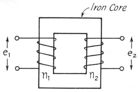
Fig. 16. A transformer for audio frequencies consists of two coils of wire wound around an iron core. The relationship between the voltages appearing across the windings is explained in the text.
Using a transformer with a turns ratio of 1.0, and connecting a source of 10 volts a.c. to one winding, nl, what power do we take from the a.c. source? None at all, if the transformer is a perfect one, because as yet there is no resistance in the circuit and consequently nothing to dissipate the power. (Actually all transformers have losses, as will be discussed in more detail later, but we'll stick with a "perfect" transformer for a while.)
Now suppose we connect a 100-ohm resistor across n2, as in Fig. 17A. From the paragraph above we know that 10 volts a.c. is appearing across n2, and 10 volts across 100 ohms means a power of 102 / 100 = 1 watt (power in watts = E2 / R). The only place this power can come from is the 10 volt a.c. source connected to n1 - nothing else in the circuit can possibly deliver power. Consequently the current from the a.c. source, and thus the current through nl, is 1 / 10 = 0.1 ampere (I = W / E). For a turns ratio of 1.0, the current through one winding is equal to the current through the other. So far as the a.c. source is concerned, it might ils well be connected directly to the 100 ohm resistor instead of to the transformer. The 10 volt source "sees" a 100 ohm load through the transformer.
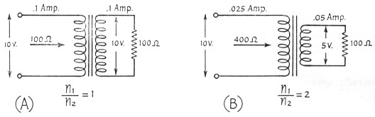
Fig. 17. Illustrating how the transformer acts to "transform" a resistance load to a different value, depending upon the turns ratio of the transformer.
But suppose the turns ratio is 2.0. For 10 volts a.c. applied to n1, 5 volts a.c. will appear at n2 and across the 100 ohm resistor. This represents a current through the resistor of 5 / 100 = 0.05 ampere. The power dissipated by the resistor is 52 / 100 = 0.25 watt. Hence the power from the 10 volt source is 0.25 watt, and the current is 0.25 / 10 = 0.025 ampere. The current varies inversely with the turns ratio, or
![]()
The a.c. source would deliver this same current and power if it were connected directly to a resistance of 10 / 0.025 = 400 ohms (R = E / I). The a.c. source "sees" a load of 400 ohms through the transformer under these conditions. The load of 100 ohms across n2 is "transformed" to a load of 400 ohms at n1 when n1/n2 = 2.0. A general expression for the effect is
![]()
In words, it means that the ratio of resistance ("impedance") transformation is as the square of the turns ratio. This is the property we will make use of in coupling the modulator to the r.f. amplifier.
The impedances given for a transformer are not what you see looking into it with no load across the secondary. In other words, the catalogs may show a transformer "10,000-ohm primary to 90,000-ohm secondary." All this means is that the turns ratio is such that 90,000 ohms connected across the secondary will look like 10,000 ohms at the primary. The same transformer with 45,000 ohms across the secondary will "look" like 5000 ohms at the primary. The turns ratio is such that an impedance transformation of 1:9 is obtained - obviously the turns ratio is 1:3. It is a good idea to use transformers designed to be used in the impedance range desired, however you wouldn't use a 500 to 200 ohm transformer for a 5000 to 2000 ohm job.
It was mentioned earlier that no transformer is perfect. Obviously the windings have resistance, since these windings consist of many, many turns of wire. The I2R losses introduced by the resistance of the windings are called the "copper losses." There are also "iron losses," which are a combination of eddy-current and hysteresis losses. The iron losses are practically constant for a given primary voltage, regardless of the current flowing through the windings. Optimum design occurs when copper and iron losses are equal under usual conditions. A close analysis of transformer operation involves drawing an "equivalent diagram" of a transformer and showing these losses as resistances, as in Fig. 18. Here ni and n2 represent the "perfect" transformer, with a turns ratio n1 / n2. The actual windings have resistance that can be measured with an ohmmeter - these resistances are represented by r1 and r2. Their effects in the circuit are obvious: current flowing through them will cause voltage drops that lower the applied voltage and the output voltage. The iron losses are represented by r0 and they depend upon the applied voltage and the design of the transformer.
The coils of the transformer have inductance, of course, and the inductance of the primary winding is represented by Lo. It is this inductance that limits the flow of current through the transformer when the primary winding of the transformer is connected to an a.c. source and the other winding is left open-circuited.
If the n2 secondary circuit in Fig. 18 were shorted at its output, the load on the transformer would be r2 and, if the ratio nl/n2 were 1.0, you would expect a load of r2 in series with rl to appear at the left-hand terminals. Such is not the case, however; when the experiment is performed it will be found that a low resistance of this order does not appear. Instead, the load appears to be higher and it shows an inductive component. This is explained by the "leakage reactance" of a transformer, represented by the inductances Lt and L2. It is a result of incomplete linking of the magnetic lines of flux through the coils - it does not contribute to the inductance of the transformer or the transfer of energy from one coil to the other.
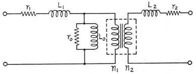
Fig. 18. An "equivalent" circuit of a transformer, showing the effects and relationship of coil resistance and inductance.
There are such things as capacity between windings and the distributed capacities of the individual windings that could have been included in the equivalent diagram, but they are insignificant at voice frequencies and would only tend to complicate the picture. The important thing to remember is the significance of "turns ratio," "leakage reactance," "primary inductance" and "winding resistance."
You can see now why it was mentioned earlier that you want to use transformers in the same general "impedance" range specified for them. A "good" transformer should have a high primary inductance, Lo, but as the turns are increased to boost the inductance, the wire resistance, r1, increases also. The transformer is designed, therefore, for a general impedance (E / I) level, which works out to be a design where copper losses equal iron losses at or near the full rating of the transformer. If the transformer is used at a considerably higher impedance level (E increased for the same I), the Lo that did a perfectly good job of holding the open-circuit current down to a reasonable value will now be incapable of doing so. Another way of saying this, and one that you perhaps know instinctively from substituting power transformers, is that they can be used at lower voltages than rated but not at voltages greatly in excess.
The primary inductance is also an important factor in the frequency response of the transformer. If the primary inductance of an audio transformer is too low, the low-frequency response will suffer because the losses of the transformer increase as the frequency is decreased, as anyone has found out who has tried to operate a 400-cycle power transformer on 60 cycles. The 60-cycle transformer is satisfactory at 400 cycles, however.
Selecting the output transformer
Getting back to the modulator, let's assume that a suitable one has been built and that we are now interested in what transformer to use between the plates of the modulator tubes and the r.f. stage we are to modulate. To determine what the turns ratio should be, you have to know two things. First calculate the load resistance presented by the r.f. stage. This is simply the plate voltage divided by the plate current (in amperes) that is supplied to the r.f. stage. For example, if the r.f. stage is one that operates at 600 volt and 150 mA (0.15 ampere), the load resistance is equal to 600 / 0.15 = 4000 ohms. (The input power is 600 × 0.15 = 90 watt, so you know the modulator should deliver 45 watt (90 - 2) and preferably 55 or 60 watt.) Incidentally, these values of voltage and current should be the actual values and not the "book" values. In other words, measure the plate voltage and current applied to the transmitter - don't just assume that you are getting 600 volts from a plate supply because you hoped you would when you built the supply.
The next step is to determine what load resistance the modulator tubes should work into. It may have been given in the article describing the design you followed. The ARRL Handbook gives the value for one particular set of operating conditions - plate voltage, grid bias - and if the plate voltage is the same or close to the value you use, the Handbook is a good reference. If you are using some other value of plate voltage on the modulator tubes, you can refer to a tube manual or tube bulletin on the particular type of tube you are using. (These manuals and bulletins are available from the tube manufacturers.) If the plate voltage you have for the modulators is something in between the typical values given by the manufacturer in his publications, the easiest approach is to take an "educated guess." In other words, if the tube bulletin shows a plate-to-plate load resistance of 6200 ohms at 400 volts and 8000 ohms at 500 volts, and your supply delivers 475 volts, call the plate-to-plate load resistance about 7500 ohms.
You now know the power the output transformer must handle (the power delivered by the modulator) and the load resistances to be matched (7500 and 4000 ohms, in the examples given). You can be very scientific if you like, and use the simple formula Turns ratio = √(R1/R2) which, for the example, would be equal to √(7500 / 4000) = √1.875 = 1.37, primary to secondary. But it won't do you much good after you have worked it out, because practically all transformer data sheets give "primary" and "secondary" impedance values instead of turns ratio. You can work out the turns ratio for various connections from the data, if you need practice in taking square roots. But to be practical about the whole thing, you're interested in finding the set of connections that come closest to the resistance (impedance) values you are using. Look at the values given for primary impedances - they might be 3000, 5000 and 8000 ohms, for example. In the secondary column, you might also find 3000, 5000 and 8000 ohms. Working out the impedance ratios available with the transformer (and neglecting step-up ratios because they don't apply in this example), you would have a list like this:
| Impedances | Impedance ratio |
|---|---|
| 8000 - 8000 | 1.00 |
| 8000 - 5000 | 1.60 |
| 8000 - 3000 | 2.67 |
| 5000 - 5000 | 1.00 |
| 5000 - 3000 | 1.67 |
| 3000 - 3000 | 1.00 |
Now comes the moment of decision. At first glance, that 8000 - 5000 combination looks closest to what you want for your 7500-4000 match, but in comparing the impedance ratios you see that the 5000 - 3000 combination actually comes a little closer. Which one should you use?
This is where a little knowledge can be a helpful, instead of a dangerous, thing. In the first place, you will recall that you are attempting to "match impedances" because that is the condition under which the modulator will deliver the full power. In other words, if the modulator doesn't work into its proper load, it won't deliver as much power as it will when correctly loaded. In the second place, if the transformer doesn't have enough turns and therefore not enough primary inductance, the efficiency will be poor at low audio frequencies. For any given transformer, you will always have to compromise between good over-all efficiency and good low-frequency response. In amateur work, the low audio frequencies are not very important, and it is usually better to sacrifice low-frequency response than to sacrifice efficiency, unless you have a modulator that is much larger than necessary.
Having reviewed the reasons behind a selection of windings, the actual choice becomes simple. We will use the 5000-3000 combination, although at first glance it may seem wrong for the job, since both values are below our actual values. We can expect to lose a little at the low-frequency end of the audio range, but it will take measurements to show it - it is hardly likely to show up on straight listening tests.
It will occur to many readers that a closer match could be obtained by changing the power to the r.f. amplifier. For example, a ratio of 7500 / 4500 is the same as a ratio of 5000 / 3000, so if we reduced the antenna coupling at the r.f. stage until we were drawing only 134 ma. (600 / 4500 = 0.134 = 134 mA), we would have an exact match. Under these conditions, the d.c. input to the modulated stage would be 0.134 × 600 = 80 watts, instead of the original 90 watts we were figuring on, and we would probably have an excess of available modulator power.
It's not really worth it. Actually, the modulator tubes will see a higher load than you have calculated, because the leakage reactance and wire resistance add to the reflected load, and it is advisable to make the load resistance slightly lower than its calculated value. If you make it too low, however, the efficiency will decrease and the power output may go down.
The driver stage
So far the design and adjustment of the modulator have been fairly straightforward. We didn't mention the class of operation of the modulator tubes because it didn't matter - the previous remarks apply to anything from Class A to Class B. However, the class of operation is quite important when considering the driver stage.
In Class AB1 operation, the modulator tubes are never driven hard enough to draw grid current, and the driver stage has only to provide sufficient voltage to swing the modulator grids. Any small tube capable of delivering the necessary voltage can be used. If the necessary voltage swing is too high or if a high value of grid leak cannot be used with the particular type of modulator tubes, transformer coupling can be used. A talking point for Class ABl operation is the ease and economy of driver design, but Class AB1 operation does not normally take full advantage of the tube capabilities. A notable exception is the 6146 - a pair of them are rated at 120 watts output in Class AB1 and 130 watts in AB2.
Another advantage of Class AB1 operation is that the bias supply is simple. All that is required is a source of negative voltage at very low current, and a potentiometer can be used to permit exact adjustment of the bias voltage. This is permissible because no grid current passes through the potentiometer - if such a bias supply were used in Class AB2 or Class B operation, the grid current would generate additional bias through the resistance of the potentiometer.
That last sentence might stand a little explanation, since it seems to be a point that confuses people occasionally. To illustrate, let's consider the grid circuit of our modulator stage, as shown in Fig. 19. Only one tube is shown, for simplicity. A source of bias, Ee, has a voltage divider across it - it is shown as two resistances, R1 and R2, for clarity, but it could of course be the usual potentiometer. The source of bias might be a battery, a VR-tube regulated supply, or any other source of voltage that does not change with the current through it. Let's say it delivers 100 volts. Then we can see that the voltage appearing between grid and cathode of the tube is
![]()
If we want 50 volts of bias on the tube, R1 and R2 could be 5000, 50,000 or 500,000 ohm (or any other values), provided they are both the same. Let's say we are using a pair of 50,000 ohm resistors. The bias voltage between grid and cathode will be 50 volt. A current of 1 mA flows through R1 and R2 from Ec. If and when the grid is driven positive with respect to cathode, grid current flows around the circuit: cathode to grid through transformer through R2 and back to cathode. This current adds to the 1 mA through R2 and increases the voltage across R2. If the grid current is small compared with 1 mA the increase won't be much, of course. However, it is obvious that the grid current flowing through R2 will change the bias and thus the operating point of the tube during the time grid current flows. The effect can be minimized by using lower values of resistance at R1 and R2, but this puts a greater current demand upon the voltage source Ec. And while we have only mentioned the effect of grid current through R2, it should be apparent that if the resistance of the secondary of the transformer is high, the d.c. voltage drop across it can raise the bias.
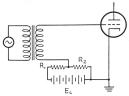
Fig. 19. When bias for a vacuum tube is derived from a voltage divider, grid current in the tube will change the bias, as described in the text.
When the grid current is encountered in a modulator, as it must in Class AB2 or Class B operation, the bias supply must be "stiff," which means that the voltage across it does not change appreciably with the current flowing through it. Dry batteries can be used for the purpose, although if high values of grid current are run the life of the batteries will not be very long. Where heavy grid currents are encountered, electronically-stabilized bias supplies are generally used.
In Class AB2 or Class B operation, when the modulator tubes are driven into grid current, the driver stage must furnish the power represented by this current dissipated in the effective grid resistance. Since the effective grid resistance is usually different than the proper plate load resistance for the driver-stage tube (or tubes), a matching transformer is required.
There are methods for calculating the turns ratio for the transformer, but they are considerably beyond the scope of any article such as this. However, that doesn't mean you can't go ahead and build the modulator. To the contrary - sensing your possible difficulty, the tube and transformer manufacturers are more than co- operative in furnishing the necessary information. The tube handbooks usually include operating information and transformer turns ratios for the tubes most suitable for Class-AB2 and Class-B service, so there is no need to resort to a formula. Suitable driver tube types are suggested, and their operating conditions are given. You will find that tubes requiring little or no grid bias - the so-called "zero bias" tubes - will be recommended for this work. The 811A is popular for modulators in the 300- to 400-watt range. The driver transformer, coupling the driver stage to the modulator grids, will have a "step-down" ratio that is dependent upon the type of driver tube, the type of modulator tube, and the operating conditions of both. The turns ratio may range all the way from 1.25:1 to 6:1. It will be given as the ratio of "primary to one-half secondary," which may be a little confusing at first. However, it comes about because only one of the modulator tubes is drawing grid current at any instant. This is illustrated in Fig. 20.
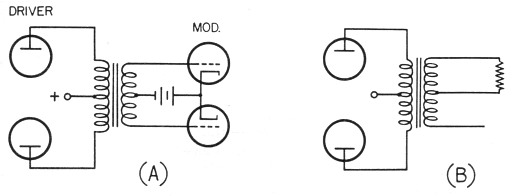
Fig. 20. When a driver stage drives a Class AB2 or Class B modulator into grid current, only one of the modulator tubes is drawing grid current at any instant. Consequently the driver load appears across only one-half the secondary winding, as shown at B.
The other consideration in choosing the driver transformer is its power-handling capability. Obviously you wouldn't use a 2-watt transformer with a 15-watt driver, if you wanted it to run cool, and you wouldn't use a 30-watt transformer with a 5-watt driver unless you already had the transformer, its turns ratio was right, and you could afford the extra space.
All this is just by way of pointing out that the catalogs and tube manuals are your best sources of information on driver transformers, and no amateur need fear that he will select the wrong transformer for the job, if he reads the catalogs carefully.
The speech amplifier
Suppose you now have a design up to a pair of, e.g., 6A3s in the driver stage. The tube manual says to run them Class A (no grid current), with a bias of - 62 volts. You know that the maximum grid swing you will need will be 124 volts peak-topeak (62 + 62 = 124). The Handbook has a table of resistance-coupled voltage-amplifier data for the common tubes, from which you can select a pair of tubes that, operated in push-pull, will give the necessary grid swing to the 6A3s. Transformer coupling can also be used of course. A little judicious study of the Handbook on the subject of speech amplifiers will allow you to select a tube line-up that will result in sufficient gain from microphone to the 6A3 grids.
General considerations
The drivers and modulators mentioned above were both triodes, but there may be instances where tetrodes would be the choice for modulator tubes. In such a case, the above considerations for matching to the load and the driver considerations still hold. The screen voltage for the tetrodes should be supplied from a "stiff" power source (one whose voltage doesn't vary radically with changes in load), because the screen current may vary from a no-signal value of around 0 up to a maximum-signal value of 15 to 60 mA. In some cases, the screen voltage can be taken from the speech-amplifier plate supply, if the required voltages are the same.
And one last word. Never attempt to test a modulator without a load on the secondary of the transformer. You stand a good chance of breaking down the transformer. You can use a resistance load in place of the (operating) r.f. stage to be modulated, but you should have a load of some kind, unless you have more transformers than you know what to do with.
Notes
Byron Goodman,W1DX.