An improved volume-compression circuit
Diode-impedance control in an "electronic funnel".
The circuit described in this article controls the over-all gain of a speech preamplifier by varying the actual signal input to the controlled stage rather than, as in more common arrangements, by varying the gain of the controlled stage. The circuit has a wide compression range and good operating characteristics.
The effectiveness of a phone transmitter can be greatly increased by taking advantage of volume compression and eliminating the low frequencies in speech. Most of the intelligibility in speech is in the range of 500 to 2500 cycles, but the power is concentrated in the range below 500 c.p.s. It is these low frequencies that modulate a telephone transmitter the heaviest, and if they can be attenuated the frequencies that carry most of the intelligibility can be boosted without overmodulating the transmitter.
By using volume compression we impart more gain to low-intensity signals than to those of high intensity. Since an intensity range of 20 to 30 dB will normally be produced by an individual talker, a volume compressor will reduce this range of signal intensities to more useful levels.
A volume compressor is a nonlinear device with loss at any time dependent upon the intensity of the input. Practical compressors are designed to have a slight time delay between the time a signal reaches the input and the time the gain is changed. The average loss is controlled by syllabic variations rather than by individual speech peaks, and is held relatively constant over syllabic intervals.
With speech, constant output levels are difficult to maintain unless some form of a.g.c. is used that follows the average (not peak) variations in normal speech. This is usually done by rectifying and filtering some of the audio output and applying the rectified and filtered signal to some portion of the amplifier to control its gain, the overall gain of the system being great enough for full output at a low voice input level. A.g.c. systems used in receivers usually change the amplification of a Class A stage by varying its grid bias in some manner. Applied to audio amplifiers, this system as a whole tends to overload easily and distorts, unless several stages are controlled at once.
The system of volume compression to be described overcomes these objections by varying the impedance from grid to ground of a single tube, and acts as a manual volume control would if it were electronically operated. The heart of the system is the property of a diode of showing decreasing impedance with an increase of current through it. A duo-diode is used in a balanced bridge circuit to control the grid impedance of a single stage much in the same manner as a manual volume control would.
Fig. 1 shows a simple circuit using a diode to control the grid-to-cathode impedance of a single stage of an amplifier. A portion of the output is fed through a transformer to a half-wave rectifier and pulsating d.c. is developed across R1. This is filtered by R2C1 and R3C2, and current is caused to flow in the duo-diode circuit. Since diodes have a characteristic of decreasing impedance with increasing current flow, this lowers the impedance to ground of point A through the balanced circuit of the duo-diode and C1 and C2. Any increase in the input signal strength to the stage will cause a decrease in signal applied to V1, with the result that the output of V1 tends to remain constant.
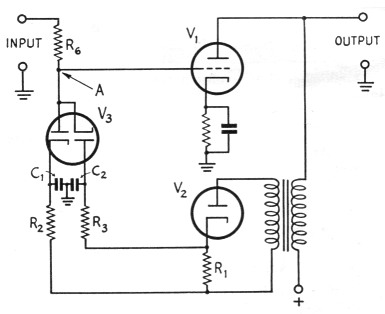
Fig. 1. The basic compressor circuit. Output from V1 is rectified by V2 and the direct current from V2 is used to control the impedance of V3. The impedance of V3 in series with R6 forms a voltage divider having an input/output voltage ratio dependent upon the impedance of V3.
Time constants
In this simple circuit no provision is made to control the point at which the a.g.c. begins to operate. Also, no provision is made for independent compression and release time constants. With a steady signal into the amplifier, a state of equilibrium is quickly reached, but over short intervals of time this condition is upset since it takes an appreciable length of time for the a.g.c. system to act after a change in input signal strength.
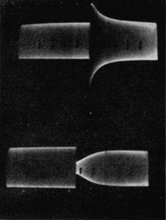
Oscilloscope pictures of compressor performance when input level is changed suddenly. Upper pattern: input amplitude increased ten times over steady level at left. Lower pattern: input amplitude decreased by factor of 10. After the change, the output amplitude returns to essentially its original value in approximately 40 milliseconds. Audio frequency 1000 c.p.s.; pattern width approximately 0.22 second.
This length of time is governed by the compression and release time constants of the a.g.c. system, the sensitivity of the a.g.c. system and the amplitude of the input signal. Low-intensity signals only slightly above the level required to operate the a.g.c. system will take considerable time to reduce the amplitude of the output to a steady-state controlled level. Signals of high intensity or a highly sensitive a.g.c. system will cause the a.g.c. to act rapidly and a steady-state condition of equilibrium will be reached quickly. This is the system's compression time.
After an exceptionally strong input signal has caused the a.g.c. to decrease the gain of the amplifier, there will be a short interval of time before the amplifier will regain its normal gain. This is its release time. Relatively low intensities into the amplifier at this time will be suppressed to a large extent and will appear in the output very weakly. In extreme cases of overload the amplifier will be dead for a short time until it can recover from the overload.
The time constant of an amplifier ordinarily is a compromise between two requirements: (1) action fast enough to control the peaks; (2) action slow enough so as not to compress later portions of speech after early portions have caused the gain reduction. A.g.c. release time must be slow enough to maintain a steady signal level; fast enough to insure quick recovery after strong signal input.
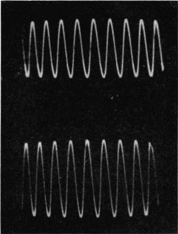
Steady-state output levels for two different input levels. The input amplitude in the lower picture is 40 db. above the input amplitude in the upper picture. The difference in output levels for these two conditions is approximately 2.5 dB.
Fig. 2 illustrates a circuit having a threshold level at which a.g.c. begins to operate and still has independent compression and release times. Batteries B1 and B2 normally charge C1 and C2 through R2 and R3. The control tube, V3, has several volts negative on its plates, thus its impedance is high and the impedance from point A to ground at its maximum. When a portion of the signal is amplified and fed back to the rectifier, V2, the current generated is used to neutralize the charge on C1 and C2. Compression time constants are determined by R1 and C1 and C2. When the charge on the condensers is neutralized, the negative voltage on the duo-diode is decreased and current begins to flow through the diodes. This current flow causes the impedance from point A to ground to decrease through the symmetrical paths D1C1 and D2C2 and acts as a normal gain control would to decrease the over-all gain of the amplifier.
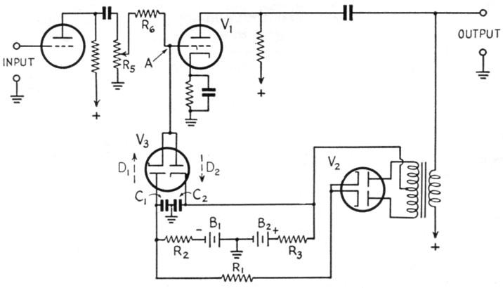
Fig. 2. A circuit in which the attack and recovery times can be separately adjusted. This circuit also provides an a.g.c. delay.
When the input signal ceases, condensers C1 and C2 charge up again from the batteries, since the feed-back current also ceases. The negative voltage on the plates of the duo-diode increases the impedance of the control tube, thus increasing the impedance between point A and ground. Release time constants are determined largely by R2 and R3 plus C1 and C2 plus the impedance of the diode. Using this system of a.g.c. the output of an amplifier can be held within 2.5 dB over an input signal range of 100 to 1. An even greater range of input signal variations can be handled by cascading two stages of diode-controlled tubes.
The photos taken off the face of a Tektronic scope with a Polaroid Land camera show the ability of the control circuit to handle large changes in input intensities with negligible distortion and still keep the output level within 2.5 db. throughout its entire dynamic range.
Operating characteristics
The rectified signal amplitude which will cause current to flow in the duo-diode is determined by the value of negative voltage from batteries B1 and B2 applied to the control tube, V3. The level of input signal at which a.g.c. will begin to decrease the gain of the amplifier is determined in part by the amount of this negative voltage. If the current through the diode cuts off when a voltage of -3.5 volts is applied to it then any lesser voltage - e.g., -2.5 volts - would cause the diode to draw current, thus reducing the gain of the amplifier even before any signal was applied to its input.
If a battery voltage greater than cut-off - e.g., -5 volts - is applied to the control tube the rectified feed-back voltage must build up to a voltage equal to the amount above cut-off before the a.g.c. action will begin. The rectified feed back signal would have to be 1.5 volts, the diff erence between -3.5 and -5 volts, before the delayed a.g.c. action would start.
Normally, the a.g.c. system is operated with a voltage greater than the cut-off value. A decrease in voltage will decrease the average controlled level. An increase in delay bias voltage will increase the average level of the controlled amplitude, since a given signal amplitude will cause less current to flow into the control tube, thus controlling V1 at a higher operating level. A decrease in the gain of V1 or the a.g.c. amplifier will also increase the average level of the controlled signal since a given input signal amplitude will cause less current to flow into the control tube. Increasing the gain preceding V1 will cause the a.g.c. system to operate with a smaller signal at the amplifier input and the average output signal level (a.g.c. controlled) will not change. The over-all sensitivity of the amplifier will be increased, however.
A practical compressor-amplifier
Fig. 3 is a diagram of a practical volume compressor designed to be placed between a crystal or dynamic microphone and the microphone input terminals of a speech amplifier. Three stages of voltage amplification are used to provide adequate gain to control the audio variations over a wide range of signal intensities.
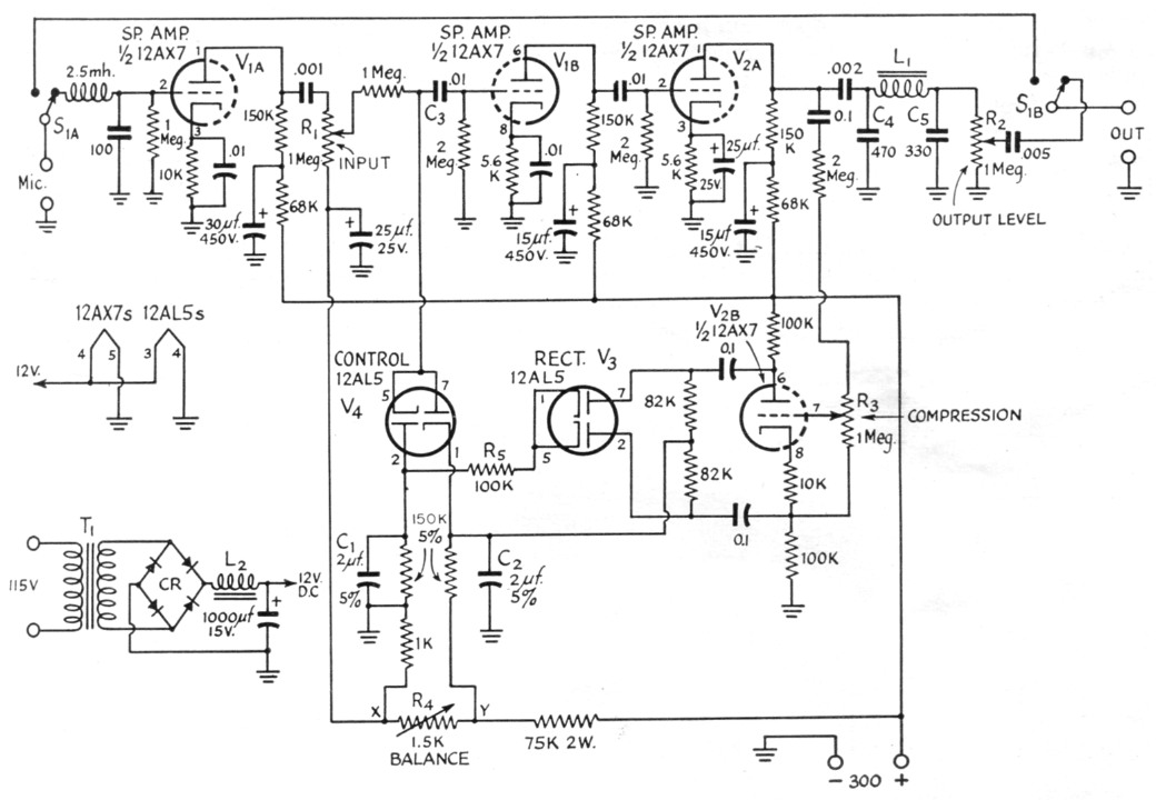
Fig. 3. Practical compression amplifier circuit, suitable for use between the microphone and a conventional speech amplifier. A d.c. filament supply is required for at least the 12AL5 control tube, as described in the text, and a suggested circuit is shown at the lower left. The current required from the 300 volt supply is approximately 5 mA.
Capacitance values are in µF for 0.001 µF and larger; pF for smaller values. Condensers less than 0.01 should be mica or ceramic. Resistors are ½ watt unless otherwise indicated.
| C1,C2 | 2 µF paper, 5 %, 100 volts (Fansteel). |
| R1,R2,R3,R4 | Potentiometers. |
| L1 | Approx. 20 H (Stancor C-1515). |
| L2 | 0.05 H, 0.6 A. |
| CR | Selenium bridge rectifier (Federal No. 1017). |
| S1 | D.p.d.t. |
| T1 | Secondary voltage 18 r.m.s., 0.6 amp. |
The input to the compressor has an L-C filter to help attenuate r.f. and a small output coupling condenser on the first stage to attenuate the low audio frequencies. A portion of the output from V2A is fed to V233 and thence to the rectifier Vg. Ripple in the output of V$ is filtered by R5, C1 and C2 before it is applied to the bridge circuit consisting of the impedances of the two diodes of V4 and the two 150K resistors. Using a voltage-divider network and blocking condenser C3 eliminates the necessity for using batteries as a voltage source for the bridge. R4 is used to balance the bridge and should be adjusted to equalize the voltage drops between ground and X and between X and Y. These voltages should be within one-tenth volt of each other. With the circuit values given, approximately 1.25 volts appear on the plates of the duo-diode. It is necessary to use d.c. on the 12AL5 filament or hum modulation will appear on V1B.
The low-pass filter, L1C4C6, causes the output to begin dropping off at about 2000 cycles and it is down approximately 10 dB at 5000 cycles. The constants of the speech amplifier are such that the response decreases below 500 cycles and is down about 13 dB at 100 cycles.
S1 is used to switch the compressor in and out of the circuit as needed. The placement of parts is not critical so long as the input wiring is separated from the power supply and any inductive hum pick-up. Shielded wire was used on the input and output leads.
To set up the compressor for normal operation an oscilloscope is a great help in showing how effectively the circuit is working and how much compression can be used before the amplifier following it overloads or distorts. Remember there is a limit to how much you can compress speech and still recognize it!
In conclusion I would like to acknowledge the aid of Ed Walker, W5KFW, without whose help the "Electronic Funnel" could not have been completed.
W.D. Brosseau, W5BSU.