A protective circuit for transmitting tetrodes
Novel dual-triode device provides variable input control as well.
Grid-leak biasing of transmitter r.f. amplifiers has the advantage of being self-adjusting, economical and simple. Its big drawback, of course, is that excitation failure removes the bias from the amplifier and may result in very high plate current and consequent damaging of the tube. The most common solution is to apply fixed bias from an external source to limit the plate dissipation to a safe value, and then obtain the rest of the operating bias from a grid leak. This requires a bias supply of some sort, an appendage many amateurs like to avoid using.
In recent years most amateur transmitter designs have used beam tetrodes in their output stages. These tubes have the characteristic that their plate current, for a given grid bias, is practically independent of the plate voltage, being instead a function of the voltage applied to the screen. Advantage is taken of this fact in the familiar clamp-tube circuit, illustrated in Fig. 1.
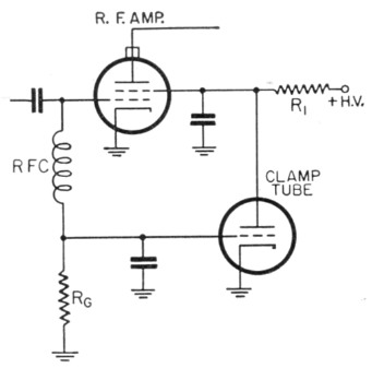
Fig. 1. Conventional clamp-tube circuit.
During normal operation the clamp tube is cut off by the bias developed across the amplifier grid leak, Rc, so it has no effect on the operation of the amplifier. Should the excitation fail, however, the clamp-tube bias drops to zero and it conducts heavily. This results in a large voltage drop across R1, and consequently greatly reduced screen voltage. The plate current is reduced to a safe value thereby.
This arrangement works well with many tetrodes, and is widely used, but it will not do the job with the 6146. This tube requires a lower screen voltage than the clamp-tube circuit will provide, in order to hold the plate current to a safe value. A common way of doing this is to insert a VR tube in series with the clamp-tube plate and amplifier screen. The tube, ignited in normal operation, goes out when the applied voltage drops, thus cutting off all voltage to the screen.
In designing a protective circuit for a new 6146 amplifier, the writer decided to try some form of series tube circuit in order to achieve a reasonably low screen voltage in case of excitation failure. The circuit shown in Fig. 2 does this, and in addition provides a convenient control of the screen voltage and plate input as well. The latter is helpful for tuning-up purposes, and is very useful as an excitation control, if the 6146 is used to drive a higher-powered amplifier.
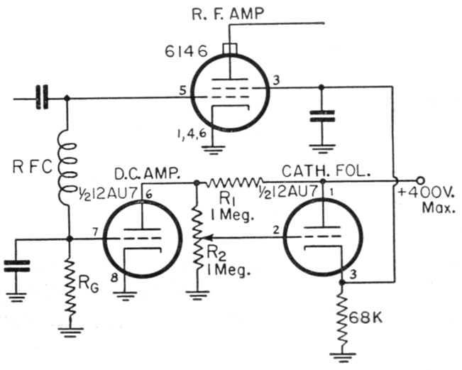
Fig. 2. Dual-triode protective circuit for 6146 or other beam tetrodes. The potentiometer R2 also controls the screen voltage under normal operation, and thus may be used for controlling the power input to the stage. R1 and the 68K resistor are ½ watt.
One half of a 12AU7 is used as a cathode follower (right side of Fig. 2), the other a d.c. amplifier. Operation of the circuit is very simple. When the 6196 is operating normally the d.c. amplifier (left triode) is cut off by the bias developed across the 6146 grid leak. The voltage applied to the cathode follower is determined by the voltage divider, R1 and R2. Its cathode follows the voltage on its grid, so adjustment of R2 allows proper screen voltage, about 150 volts, to be applied to the amplifier. Should the drive to the 6146 fail, the bias on the d.c. amplifier will drop to zero. It will then conduct, and the drop across RI will reduce its plate voltage to a low value. This low voltage will then be applied to the 6146 screen through the cathode follower.
Using the circuit values shown it is possible to reduce the screen voltage to approximately 20 when the drive is lost. This will keep the plate current of the 6146 low enough so that the plate dissipation of the tube will not be excessive. This circuit has several advantages over the more conventional clamp-tube arrangement:
- The screen voltage may be adjusted without affecting the bias by varying R2, thus providing a convenient power input control for testing, tuning up, local QSOs or holding the power under the figure specified for certain multipliers in contest operating.
- The twin triode does double duty, replacing the high-wattage screen resistor and the protective tube.
- It is possible to reduce the screen voltage to very low values during excitation failure by making R1 and R2 high resistances. With the conventional circuit the only way to lower the screen voltage is to reduce the resistance of the clamp tube.
This circuit may be adapted for other screen voltages by changing the ratio of R1 to R2. For tubes requiring higher screen voltages, the 6AS7G or 6BL7GT would appear to be logical choices in place of the 12AU7.(1) Although it has not been attempted, there seems to be no reason why this circuit could not be used in a plate-modulated amplifier by inserting an audio choke in the screen lead to the amplifier.
The 6146 could be screen modulated by adjusting R2 to reduce the screen voltage to half the c.w. value, and then applying the modulating voltage to the grid of the cathode follower through a 0.01-4 condenser. Since the output impedance of the cathode follower is low, the voltage at the screen of the amplifier will follow the input audio voltage faithfully, and thus should result in somewhat more linear modulation than is possible with ordinary clamp-tube modulation.
Notes
- If the circuit of Fig. 2 is used exactly as shown, some attention must be paid to the peak heater-cathode voltage rating of the tube used as d.c. amplifier and cathode follower, since it establishes a limit to the screen voltage of the r.f. amplifier. For example, the 12AU7 is rated at 180 volts, the 6BL7GT at 200 volte, and the 6AS7G at 300 volts, peak heater-cathode voltage. If the heater-cathode voltage rating would be exceeded, the d.c. amplifier and cathode-follower functions can be assigned to separate tubes, and the cathode-follower heater supplied by a separate transformer winding, one side of which is also connected to the cathode. - ED.
Thomas E. Beling, W9AEI/2.