Two-dial receivers and 100 Kc. signals
Pointers on using frequency standards.
The little 50/100-kc. frequency standard of W2JN, described in the July issue of QST, brought to mind that perhaps not everyone appreciates the usefulness of such a device or knows how to use it. This was forcefully brought home recently while watching several different operators "setting" various ham bands on a new two-dial receiver they were torturing. A 100 kc. oscillator was included in the receiver, but only the "savvy" operators used it or knew how to - the others ignored it.
The 100 Kc. frequency standard
A number of the current receivers either incorporate a "Calibrator" or "Crystal Calibrator" or else make provision for one as an additional feature. The "Calibrator" is a crystal-controlled 100 kc. oscillator, designed to be rich in harmonics. Such 100 kc. oscillators can also be built(1) and used with any receiver. One is a mighty handy little device to have around the shack, because it will enable you to sneak up close to the edge of a band with your transmitter, if you have the courage of your convictions about your ability to use the gadget. Let's see what it does and how to use it.
If the 100 kc. standard gave no harmonic output, its output would be plotted against frequency as is shown in Fig. 1A. There would be a signal from the oscillator at 100 kc., and no energy from it at any other part of the radio spectrum.
But Fig. 1A was just a theoretical idea, because almost any practical oscillator that you might build would have a lot of harmonics. This can be represented by Fig. 1B, which shows signals every 100 kc. Those near 1C0 kc. will be louder than those at higher frequencies, and thus the 35th harmonic (at 3500 kc.) will be weaker than the 2nd harmonic at 200 kc. We will assume that the oscillator we're using has harmonics we can hear up to 30 Mc. - some oscillators would have and some wouldn't.
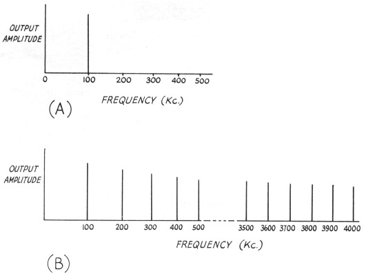
Fig. 1. (A) A pure (no harmonica) 100 kc. oscillator would give output only at 100 kc.
(B) The actual output from a 100 kc. oscillator is rich in harmonics, and it furnishes "marker" signals every 100 kc. down through the spectrum.
So far, you should have a mental picture of a 100 kc. oscillator that, when it is turned on, generates signals at every multiple of 100 kc. Fig. 1B is such a picture. Now ask yourself what happens if the 100 kc. oscillator is not on 100 kc. but is oscillating at 100.1 kc. Instead of signals appearing at 200.0, 300.0, 400.0 and 500.0 kc. (and also 3500.0, 3600.0, etc., kc.), the signals now show at 200.2, 300.3, 400.4 and 500.5 kc. (and at 3505.3, 3603.6, etc., kc.). The error in cycles increases by the order (number) of the harmonic, so a 0.1 kc. error in our oscillator at 100 kc. gives an error at the 35th harmonic of 3.5 kc. This is the second mental picture to retain: A small error in the oscillator can give a large error at a high harmonic.
We don't have to run screaming into the night at this apparent disadvantage of a 100 kc. frequency standard - let's turn around and make it work for us. It's easy. Stop and think about how you are going to check the standard. WWV? Right. (We have to assume that WWV's signal is correct, and they do have a pretty good record.) If you use the WWV signal at 5000 kc., you will be comparing that standard against the 50th harmonic of your oscillator. And let's say that a 50-cycle beat note is the lowest you can ever hear out of your receiver, because of limitations in its audio system and your hearing. (Actually, you might do a little better than this, but it makes the arithmetic easier.) If you adjust your 100 kc. crystal standard to the point where you can no longer hear a beat note between its harmonic and the unmodulated signal from WWV, you know that your standard is within 50 cycles of being right at 5000 kc., which makes it within 1 cycle of being right at 100 kc. That's pretty good precision for a simple little gadget.
You may have noticed that an unmodulated signal from WWV was suggested. Most of the time WWV sends a standard tone and some time ticks, and every five minutes there is identification and some voice, but there is a short period following the announcement when there is no modulation, and that's the time it's easiest to check your standard. The receiver will be set up for 'phone (b.f.o. off) and tuned to WWV. When your 100-kc. oscillator is also running, there will be an audible beat between its 50th harmonic and WWV (if you're tuning in WWV at 5 Mc.) if the oscillator is not within 1 cycle of 100.000 kc. Swing the adjustment trimmer on the frequency standard through the zero-beat condition and leave it halfway between the settings where you just start to hear a low tone.
Some day you may want to learn the more precise methods for setting your frequency standard, as can be done with the b.f.o. on or with an oscilloscope, but the method just outlined is quite good for all but the most precise measurements.
When you first acquire a 100 kc. standard, you will probably want to check it every day or so, to see if it is stable and relatively insensitive to temperature changes. After familiarizing yourself with its particular habits, you can check it once a week or once a month, or whenever you are going to sneak quite close to the edge of a band. You now know how to check it, you know how well you can depend upon it, so you can work close to the edge if you have confidence. But don't get caught outside! The FCC won't listen to your claims that WWV must have drifted a little.
Setting up a receiver
It should be rather obvious now how you could check the frequency calibration of a receiver. All you do is turn on the 100-kc. oscillator and tune across the band being checked. If the signals from the standard appear at the 100-kc. intervals marked on the receiver dial, the receiver calibration is right. If they don't coincide, the receiver is wrong. In some cases you can do something about it, and in some you can't.
If, for example, you are using a single-dial continuous-coverage receiver like the BC-348, all you can do is to observe how much (if any) the calibration differs from the exact frequencies indicated by the 100 kc. oscillator harmonics. For future reference, you can make notes on these differences within an amateur band or, if you know your receiver, readjust the receiver oscillator trimmer to set the calibrations "on the nose." In some cases, you will find that if you reset the receiver-oscillator trimmer so that the dial reads right at 4.0 Mc., for example, it will be off at 3.5 Mc. In a case like this, the only cure is to bend plates on the tuning condenser. While this can be done, we recommend it only to brave souls who know what they're doing and understand receivers pretty well.
The two-dial receiver
A more common case one may run into is that of the two-dial receiver, where one dial is called "bandset" and the other is called "bandspread." This is a flexible type of receiver that, when used with a 100 kc. frequency standard, can always be set up to give you one amateur-band edge very accurately. Let's spend a little time with it.
First off, you must realize that it is the "high-frequency oscillator" tuning of the receiver that determines the frequency to which the receiver is tuned. Fig. 2A shows in simple form the input circuits of a typical receiver. A 500 kc. i.f. amplifier is assumed (to make the arithmetic easier). When the receiver is set to receive a signal at 3800 kc., the r.f. and mixer circuits should be tuned to 3800 kc. If they are off slightly, the signal will not be amplified as much, but that's the only effect. (You've noticed this when you have twisted the "Antenna Trimmer" of a receiver - it changes the volume of the signal but doesn't detune it.) But the oscillator must be on 4300 kc.(2) to heterodyne the 3800 kc. signal to 500 kc. - any error here would heterodyne some frequency other than 3800 kc. to the 500 kc. i.f. To clarify, let's say the oscillator is on 4305 kc. The signal at 3800 kc. will be heterodyned to 505 kc., while a signal at 3795 will be heterodyned to 500 kc. Hence it is the intermediate frequency and the high-frequency oscillator frequency in combination that determines the signal we will be tuned to. Since the i.f. is tuned at the factory and left fixed at one frequency, it is the high-frequency oscillator tuning that is all important.
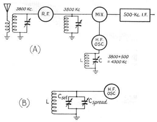
Fig. 2. A block diagram of a receiver tuned to 3800 kc. is shown at (A). If it is a two-dial receiver, the oscillator tuning (and also the r.f. and mixer tuning) is done with two condensers in parallel, as shown in (B).
In a two-dial receiver, the high-frequency oscillator condenser is actually two condensers in parallel. In other words, C in Fig. 2A would show up on the schematic of a receiver as two variable condensers in parallel, as in Fig. 2B. Now suppose that with the inductance L, we require 100 pF of C to tune to 4300 kc. When we have the two condensers in parallel, it is obvious that they can be set in a number of different ways to give a total of 100 pF. For example, if Cset were set at 80 pF, we would be tuned to 4300 kc. with Cspread at 20 pF. Or we could use an 81 + 19, 82 + 18, 83 + 17 or 78 + 22 combination.
Now think of a scale calibrated in kc. attached to Cspread. For convenience, this scale is going to coincide with the frequency we're supposed to be listening to, not the actual frequency of the receiver oscillator. In this case it might read 3800 kc. at a capacity value of 20 pF. Thus, in order for us to actually hear a 3800-kc. signal at this setting, the bandset condenser, Ceet, would have to be set to give a capacity of 80 pF., since we need that total capacity of 100 pF. to be on 4300 kc. with the high-frequency oscillator.
Now let's be really nasty sometime when you aren't looking, and loosen the setscrew on your bandspread condenser and move the scale around a bit. It might end up so that 3800 kc. on the scale coincides with a capacity of 18 pF instead of the original 20. If you left the handset condenser as it was before, corresponding to a capacity of 80 pF, you would no longer be tuned to 4300 kc. For a bandspread-dial setting of 3800 kc. you would actually be listening to a slightly higher frequency, since the high-frequency oscillator circuit now has a total C of 80 + 18 = 98 pF instead of the required 100.
What to do about it? You could dig into the set and fix the scale on the shaft the way it was before we sabotaged it for you, but there is a much easier way. Just move the handset condenser a little, so that it corresponds to a capacity of 82 pF, and now your total C is back to 100 pF and the band-spread scale reads correctly.
All this long rigmarole is for only one purpose: To fix in your mind that the bandspread dial can be made to read absolutely correct at at least one point by proper setting of the handset condenser. And you really don't care what the handset condenser scale says - you're only interested in reading the bandspread dial.
Actually, we have no intention of sneaking into every hamshack and changing the bandspread scales on receivers. We don't have to. We can leave that job to manufacturing tolerances, temperature and humidity, and aging. But why worry about it? You can always set the scale on the nose at at least one point by a change in the handset condenser. If you have a 100-kc. frequency standard, you will always have 100-kc. check points for the job. The logical procedure, of course, is to set up the bandspread dial so that it reads "on the nose" on the band edge closest to where you are operating at the time.
But suppose that you set up the receiver so that it indicates 3500 kc. "on the nose" and you find that 3600 and 3700 kc. don't come out exactly right? You can worry if you want, or you can bend the condenser plates as outlined earlier. But the simplest procedure is to note whether these points are reading "high" or "low" and how many kc., and file the information for future reference. What you have actually done is to recalibrate the receiver - you now know that when you're "on the nose" at 3500 kc., the receiver reads so many kc. high (or low) at 3600 and 3700 kc. By following the same procedure from all band edges, you are all set.
One last point. When you get to 21 and 28 Mc., you may have trouble determining whether a signal from the 100 kc. standard is 28.000 Mc. or 28.100 Mc., for example. There's a simple way out. With a crystal or VFO signal in the low-frequency end of the 80-meter band, you can use its 8th harmonic to cross-check. Say you have a crystal at 3600 kc., or you have a VFO that can be set there. (The VFO can be set "on the nose" by cross-checking against the 3600-kc. from your 100-kc. standard.) Now set the bandspread dial at 28.800 Mc. (8 × 3600 = 28,800) and tune with the handset dial until you hear the crystal or VFO harmonic. You now know that you're close to right, so turn on the 100-kc. standard and listen for its harmonic around 28.800 Mc. and then work back up the band. In other words, the 100 kc. standard harmonic closest to the VFO harmonic will be 28.800 Mc. The next lower one will be 28.700 Mc. and so on. If, when you get to 28.000 Mc. the bandspread dial reads a little off, you know what to do. Working the two dials together, so that you won't jump from the 28.000-Mc. harmonic to the next higher or lower one, keep the signal in tune as you set the bandspread dial closer to 28.000 Mc. and compensate with the handset dial. Then log the setting of the handset dial for future reference, so that you can come close to the right setting before you put it "on the nose" with the signal from your 100 kc. standard.
If you have a 100 kc. standard and a 1000 kc. standard, you can pick up most band edges easily (at the low-frequency ends) with the harmonics from the 1000 kc. standard, but the method just outlined is simply a "poor-man's version" of the same general procedure.
When you have familiarized yourself with the above procedure, you should have a better understanding of frequency standards and two-dial receivers. You will appreciate that a bandspread dial calibration may be correct over an entire band but it is more likely not to, unless you want to pay a lot more for the receiver. You should also recognize that you can always bring at least one point on the scale into exact calibration by a proper setting of the handset condenser.
And finally, to get back to the W2JN frequency standard, you may want to convert your present 100-kc. standard to this newer circuit, to give you check points every 50 kc. and thus be able to mark band edges and subband edges that you can't hit with the straight 100 kc. standard. You use it the same way that you use the 100 kc. signals, of course.
Notes
- Examples other than the W2JN oscillator in the July issue include the one in Chapter 21 of The Radio amateur's handbook. An excellent article on frequency standards is Collier, "What price precision?", QST, Sep. and Oct., 1952.
- It could also be on 3300 kc., but most receivers put the oscillator on the high-frequency side in this range.