A variable bandwidth filter
Double conversion with dual filter for continuously variable selectivity.
The system described here should appeal to the experimentally-inclined "skirt-selectivity" fan who wants the frequency separation between his steep sides to be adjustable. By inverting the signal with double conversion, two identical, but unsymmetrical, filters can be used in such a way as to take advantage of the steepest side slope in each, thus giving a symmetrical steep-sided pass-band.
Better selectivity in amateur receivers has been continuously sought from very nearly the beginning of amateur radio. The necessity for improved receiver selectivity has followed fairly closely the number of active amateurs in the various bands. Today, more than ever, a really selective receiver is essential.
Receiver selectivity can readily be shown by plotting a response curve, using frequency (usually the i.f.) along the horizontal axis and signal output (usually in dB) for the vertical axis. The curve for a typical superheterodyne receiver is shown as the dotted line in Fig. 1. A theoretically ideal curve is also shown in Fig. 1 as a solid line. It will be noted that the ideal curve is flat on top and has vertical sides. The vertical sides are by far the most important consideration since the slope of these sides determines how close in frequency two signals can be without mutually interfering.
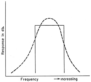
Fig. 1. Representative i.f. selectivity curve (dashed line) and "ideal" curve (solid) having the same effective bandwidth.
However, Fig. 1 does not show another most important and desirable feature of an ideal curve. This is the width between the vertical sides, which should be only as great as necessary to accommodate the particular type of signal being received. For c.w. reception, the curve can be quite narrow, its width depending mainly on receiver and transmitter stability, while for phone reception it should be about 3000 cycles wide. The ideal response curve, then, should have nearly vertical sides, be fairly flat on top and should be capable of being varied in width from zero to 3 kc. or more. A device has been constructed which, when added to almost any superheterodyne receiver, will closely approximate this ideal curve. The following paragraphs describe the evolution of the device.
Crystal-filter characteristics
In connection with the construction of a single-sideband transmitter last year, considerable experimenting was done with filters using surplus FT-241 crystals. One of the conclusions reached as a result of these experiments was the fact that an amazingly sharp cut-off could be obtained by using shunt crystals, à la W1JEO(1), in connection with either half-lattice (two crystal) or regular (four crystal) filters. Fig. 2 is representative of the best curves obtained by this method.Fig. 3 shows the arrangement found simplest and still capable of producing a very sharp cut-off. In Fig. 3, crystals A and B should be separated by about 3 kc. and crystal C should be almost exactly the same frequency as the higher of A and B. Crystal C should be adjusted until the steepest slope is obtained. Adjusting upward in frequency is done by edge grinding the crystal and lowering the frequency can most readily be done by copper plating. The other crystals shown by dotted lines in Fig. 3 are added at such intervals as are found necessary to prevent the response curve from rising at frequencies higher than the cut-off point of the curve.
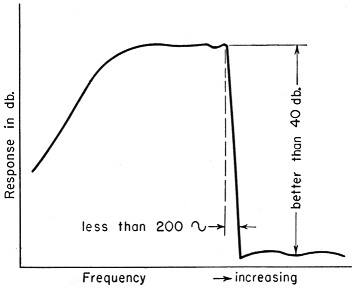
Fig. 2. Type of selectivity curve obtained with half-lattice crystal filter and shunt crystals.
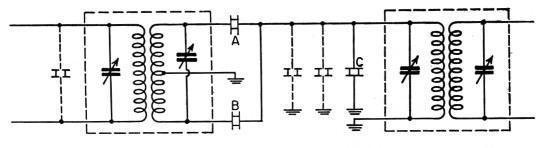
Fig. 3. Filter circuit using shunt crystals.
The possibility of using these filters in receivers was considered but the idea was discarded since it was found that the filters were never symmetrical. Any adjustments which steepened one side of the passband always resulted in loss of steepness on the other side. However, the fact that we could obtain a drop in response of 40 dB in less than 200 cycles was startling enough to make a deep impression.
Variable selectivity
Some time later, we were fortunate enough to run across the basic principle used by a commercial concern in a variable bandwidth filter(2). It was immediately apparent that this principle could be used with our lop-sided filters to make an excellent "gadget" for our receiver. The device was constructed and the results were so astonishing that it was decided to pass along the basic idea.
Fig. 4A is a block diagram showing the principle of operation. The major items required are two filters, F1 and F2, four mixer stages, M1, M2, M3 and M4, and one variable frequency oscillator, VFO. The filters are as nearly alike as possible, using FT-241 surplus crystals in the vicinity of 375 kc. M1, M3 and M4 are true mixers, with M1 and M4 being fed the fundamental frequency from the VFO, and M3 being fed the second harmonic from the VFO. M2 is more properly a converter, with its oscillator portion preferably controlled by a crystal whose frequency is twice the i.f. of the receiver. The VFO is a pentode with the first two grids and the cathode comprising the oscillator which provides the injection frequency for M1 and M4. The plate circuit of the VFO acts as a frequency doubler and produces the proper injection frequency of M3. A series trap to ground, tuned to the oscillator fundamental, is essential in the plate circuit to prevent the fundamental frequency of the VFO from appearing at mixer M3.
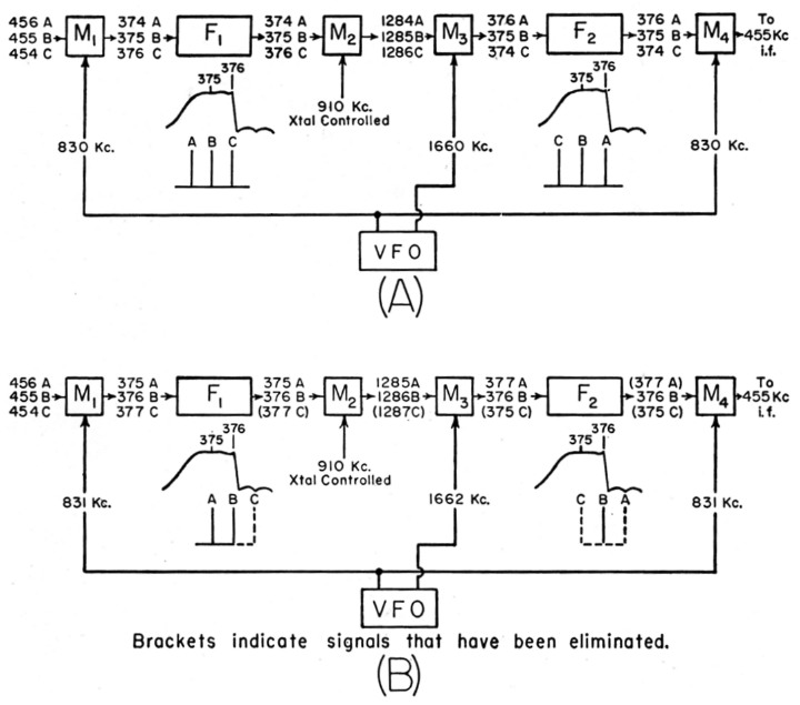
Fig. 4. Operation of the variable bandwidth circuit. Comparison of A and B shows the effect of varying the VFO frequency.
To describe how this circuit operates, let us assume that it is desired to receive one signal (c.w. in this case) from a group of signals extending one kilocycle on either side of the wanted signal. In order to more clearly follow these signals through the block diagram, we will designate the wanted signal as B and the extremes of the interfering signals as A and C, A for the high-frequency side and C for the low-frequency side. If B is tuned in on the nose with a receiver whose i.f. is 455 kc., then A, B and C will enter the device with frequencies of 456, 455 and 454 kc., respectively. These signals are shown in Fig. 4.
If the designed cut-off frequency of the filters is 376 kc., then for the purpose of describing the operation, the "center" of each filter can be considered to be 375 kc. This establishes the normal frequency of the VFO as 455 plus 375, or 830 kc. With 830 kc. injected into M1, signals A, Band C enter the first filter, F1, at 374, 375 and 376 kc., respectively. All three will be passed by F2 and will appear at the input of M2. The signals are shown relative to the curve of the filters just under the blocks F1 and F2 in Fig. 4.
At this point it becomes necessary to reverse the signals with respect to F2. In effect, we reverse F2 with respect to the incoming signals so that the steep side of F2 will act as the "back end" .of the steep side of F1. M2 and M3 are used for this purpose by first "beating up" and then "beating down."
Since M2 has an oscillator frequency of 910 kc. (twice the i.f. of the receiver), signals A, B and C leave M2 at 1284, 1285 and 1286 kc. and appear at the input of Ms. With an injection frequency of 1660 kc. from the plate circuit of the VFO, M3 converts the signals to 376, 375 and 374 kc., respectively, and they will pass through F2 as indicated. Note that in F1, signal C was adjacent to the steep side of the filter, while in F2, signal A was closest to the steep side. Any signals beyond A or C have been eliminated in one or the other of the filters. In effect, we have passed the signals through a filter which has very steep front and back slopes and whose width is 2 kc.
Now consider Fig. 4B. It is identical to Fig. 4A except that the frequency of the VFO has been increased to 831 kc. The incoming signals have been partially shifted out past the steep side of F1, thus eliminating all signals between B and C, including C. If the injection frequency to M3 had remained unchanged, the signals would have shifted lower in F2 because of the reversal process. However, since we also want to shift the signals out through the steep side of F2, we must recover the 1 kc. shift caused by shifting the injection to M1, as well as moving another 1 kc. in the proper direction. This is the reason for supplying M3 with the second harmonic of the VFO. By this process, all signals from B to and including A are eliminated in F2. We now have, in effect, a filter with very steep sides and one whose width has been narrowed down to accept only the one desired c w. signal. It can be seen that by varying the VFO, we can effectually determine the bandwidth of the response curve at will, from zero to the designed width of F1 and F2.
M4 is used to return the signals to the original i.f. of 455 kc. for reinsertion into the receiver. M4 is not required if a separate i.f. strip, second detector, and b.f.o. are used to follow F2. In this case, some provision should be made to permit gain control in the device. With the device as shown, the gain of the mixers is just about enough to equal the losses in the filters and the receiver functions normally with the usual a.v.c. operating as intended. The input to the variable filter is taken from the output of the first i.f. stage and the output is returned to the input of the second i.f. stage.
Simplification
As described, the variable bandwidth filter operates in such a way that a signal tuned on the nose remains in the center of the filter regardless of the bandwidth setting. If this feature can be dispensed with, considerable simplification of the device is possible. The simplification requires that F1 be designed for a "center" frequency equal to the i.f. of the receiver. M1 and the separate VFO can then be eliminated and the signals are moved in and out of F1 by tuning the receiver itself. M3 becomes a converter with its oscillator portion capable of being varied and its frequency adjustment determines the bandwidth of the response curve. It must be kept in mind that the steep side of F1 remains stationary with respect to the signal, while the steep side of F2 is, in effect, moved back and forth. Under these circumstances, narrowing the filter may cause loss of the signal unless the receiver is also retuned.
Suggestions
Since this article is intended only as the presentation of an idea, no design or construction details are given, although the circuit of Fig. 5 will serve as a starting point for work with the device. Some pointers are in order, however. Shielding of the components and wiring is of the utmost importance and the frequencies involved must be given due consideration. Adequate by-passing is a must. Any kind of coupling around the filters will diminish the effectiveness of the device.
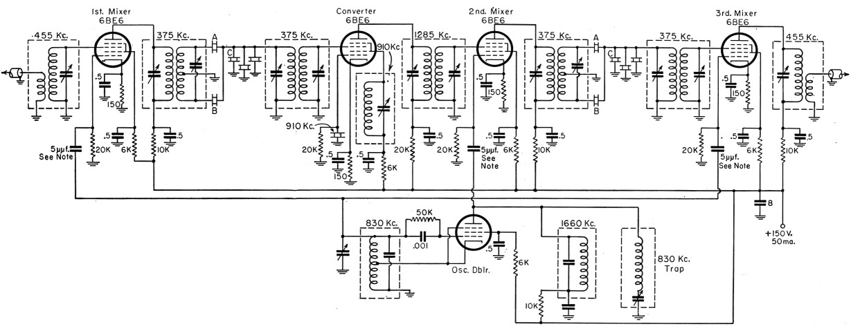
Fig. 5. Suggested circuit for an adapter to be used with a receiver having an i.f. of 455 kc. For the 375-kc. circuits the author used 455-kc. i.f. transformers with capacity padding. The i.f. transformers in the receiver were modified for low-impedance output and input for coupling into and back from the adapter.
Nom: Adjust the 5 pF condensers to give -10 volts from 6BE6 oscillator grid to ground, as measured by v.t.v.m.
Mechanical filters can be used for F1 and F2 but since they are relatively expensive, many amateurs will elect to construct these items. Half-lattice filters are recommended in this case since it is much easier to use only two noncritical surplus crystals than it is to match the pairs of crystals required by the full lattice. Better results are obtained with the full lattice filters but the extra effort is hardly worth the small improvement.
If the filters are properly built to give the sharp slope, and reasonable care is taken in the construction of the device, it will be a real source of pleasure. It will make a top-notch receiver out of even a poor receiver. For ordinary phone reception the variable feature is superb, and of course it is a natural for the "duck chatter" boys.
Notes
- Edmunds, "A crystal filter S.S.B. exciter," QST, November, 1950. See also,
Good, "A crystal filter for phone reception," QST, October, 1951. - The manufactured unit to which the author has reference here is the MCL-50 Signal Splitter, produced by the J. L. A. McLaughlin Corp., La Jolla, Calif. The basic principle of varying selectivity described here is of somewhat obscure origin but has appeared, apparently quite independently, at intervals and in different places. The idea of using the second harmonic of the oscillator to give variable bandwidth with constant center frequency is, so far as is known, original with the author. - En.
H.E. Thomas, W6CAB.