Remote end-fed antenna with coaxial line
Data on antenna system bandwidths.
Here is some interesting information on a well-known antenna system that should generate new interest in end-fed antennas. It should also help to overcome some of the aversion to antenna couplers, since it indicates that the trouble with antenna couplers may not be the couplers but the operators who misuse them.
In a great many amateur radio station locations it is more convenient to use the end-fed antenna than it is to use the center-fed antenna. Most articles that have appeared in amateur publications describing the end-fed antenna show the circuit as in Fig. 1. Then the articles usually go on to tell of its principal shortcomings, some of which are as follows: High r.f. voltage is brought into the shack where it can give much trouble such as r.f. feed-back, etc.; also, the antenna is tightly coupled for all the harmonics. These shortcomings can be overcome to a great extent by remotely feeding the antenna through coaxial cable. Those articles devoted to remote end-feeding the antenna usually show a circuit similar to that in Fig. 2. The articles that have come to the attention of the author give no information as to what portion of a band might be covered without retuning the antenna tank circuit and still maintain a flat feed line. The location of the writer's station is such that an end-fed antenna for the 80 meter band is convenient, so one was installed to be used temporarily and has been in use here for two years. The circuit is shown in Fig. 3.
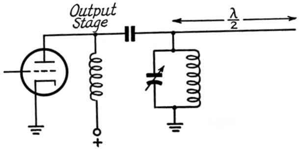
Fig. 1. A half-wavelength antenna can be fed by connecting it to the plate tank circuit of the output stage. This often leads to trouble from r.f. feed-back.
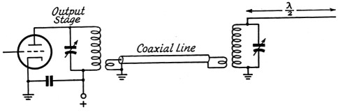
Fig. 2. An additional antenna-coupling circuit, coupled to the transmitter through a low-impedance line, overcomes the shortcomings of the circuit in Fig. 1 but usually introduces some new ones.
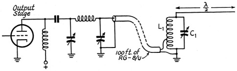
Fig. 3. Another version of the circuit of Fig. 2, asused at W5SQT.
After using this system and getting the feel of it, and also getting very good reports on it, I decided to run some s.w.r. curves on this antenna. Before this was done, however, it was observed that the farther the operating frequency departed from the frequency to which the antenna was cut, the more often the antenna tank had to be retuned to load the transmitter properly. This, of course, was expected. In the vicinity of the frequency to which the antenna was cut, the final amplifier loaded well for a bandwidth of about 100 kc. without having to retune the antenna tank. The antenna under discussion is 125 feet long and 20 feet high, in the form of an inverted "L." Its resonant frequency is 3770 kc. It is end-fed through a tank circuit as shown in Fig. 3 by 100 feet of 52-ohm coax. The circuit is adjusted so that the antenna tank hits resonance at 3770 kc. with C1 at a value of approximately 135 pF An s.w.r. bridge (built according to ARRL Handbook) was used to make the s.w.r. measurements. The purpose of the measurements was to find out what bandwidth could be had without retuning the antenna tank and still have a flat transmission line. A flat trans- mission line is defined here as one having an s.w.r. of 2 or less. The resulting curves are shown by Fig. 4, Fo being the frequency for which the antenna is resonant. The first set of measurements was made by setting the tap on L1 and the condenser C1 (Fig. 3) until an s.w.r. equal to 1 was obtained at 3770 kc. Then the antenna tank circuit was left set at this value, the frequency was varied, and the s.w.r. noted at several frequencies. The results were plotted to give curve A in Fig. 4. The frequency of the VFO was then set at 3900 kc. and the antenna tank readjusted until the s.w.r. was a minimum (the tap on L1 was left as set originally). The VFO was then varied without the readjustment of the antenna tank, and the s.w.r. was noted and plotted, to give curve B. This process was repeated for the data shown by curves C and D. As can be seen from curve A, a bandwidth of over 100 kc. can be covered without retuning the antenna tank circuit, and the s.w.r. remains at 2 or less. Examination of Fig. 4 also shows that the broadest frequency response is around the frequency to which the system is matched.
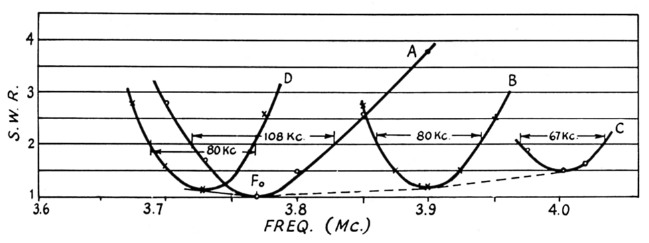
Fig. 4. A plot of s.w.r. vs. frequency for an antenna cut to 3770 ka (Fol and tuned at various points through the 80-meter band.
Fig. 5 shows the bandwidth plotted against frequency. For all practical purposes the frequency to which the antenna is cut can be anywhere in the 80-meter band and the curve will still apply to the relative bandwidth of the system, so long as the Q of the antenna tank is about 8 or 10.
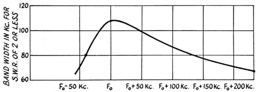
Fig. 5. Using the data in Fig. 4, this plot of band. width vs. departure from the resonant frequency is obtained.
To demonstrate the practical use of the curves, the following examples will be explained. Let us suppose you wish to work the low end of the 80 meter c.w. band - you could cut the antenna length to, say, 3550 kc. Tune up the system as previously described and you are ready to work from 3500 to 3600 kc. without retuning the antenna tank circuit. Now, if you wish to work this antenna to a frequency as high as 3700 kc., it is only necessary to make another setting of the antenna tank condenser Cl. Referring to Figs. 4 and 5, let Fo = 3550 kc. The bandwidth is 108 kc. (3608-3500). The initial setting of C1 for s.w.r. = 1 should be noted. This leaves 92 kc. to be covered to get to 3700 kc. Now set the VFO at 3658 (3658 = Fo + 108). Adjust condenser C1 to give a minimum s.w.r. (this should be about 1.1), and note the setting of C1. With two fixed settings of C1, we can cover 3500 to 3700 kc. on the c.w. band. These settings can be made manually or by one of the many possible electromechanical means. By the same procedure, the entire 75 meter phone band may be worked by cutting the antenna to resonance at 3850 kc. and finding two settings for C1, at 3850 and 3954 kc., respectively, by following the previously described procedure of adjustment. The antenna in use here was cut to work in the high end of the 80 meter c.w. band and the low end of the phone band. For those who might like to duplicate this antenna, the values for the antenna tank circuit are: C1 = 150 pF, Ll = 16 turns No. 16 wire 2U-inch diam. and 1.5 inches long. The coaxial line is tapped on 1.5 turns above the ground or bottom end.
Application to other bands
Since Fig. 5 is essentially a plot of selectivity against frequency, it can be assumed that bandwidth as indicated will increase directly in proportion to the frequency. That is, the bandwidth at 7 Mc. equals twice the bandwidth at 3.5 Mc., and the bandwidth at 14 Mc. equals 4 times the bandwidth at 3.5 Mc., etc. Although no detailed measurements have been made by the author to obtain empirical data on higher frequencies, practical results obtained using this method of feed for a half-wave vertical antenna on 7 Mc. and a half-wave vertical antenna on 14 Mc. tend to substantiate this assumption. The maximum bandwidth for one setting of C1 on 7 Mc. was approximately 200 kc., and the maximum bandwidth for one setting of C1 on 14 Mc. was 400 kc. Practical values for C1 were 70 and 35 pF for 7.15 Mc. and 14.2 Mc., respectively. The spacing between the plates of condenser C1 should be equal to or greater than the spacing of the condenser plates used in the final amplifier tank circuit. Although it is not necessary to ground the low end of the antenna tank circuit, it is advisable to do so as a measure of protection from lightning. This system of feed gives a measure of safety when used with the pi network, since it places a short across the plate circuit of the final amplifier in the event of a faulty blocking condenser.
The antenna tank used in these measurements rests on a steel oil drum 22 inches high and 15 inches in diameter. The drum sits on the ground, so the ground lead is therefore the oil drum. If the antenna tank is insulated from the oil drum, it has only a slight detuning effect on the antenna tank and may be compensated for by slightly retuning the antenna tank circuit. Various lengths of coax from 8 to 100 feet have been tried here both with and without a ground directly at the base of the antenna tank circuit. However, a direct ground is recommended. A rod driven in the ground with a lead 24 inches long gives the same results as the oil-drum ground.
J.L. Copeland, W5SQT.