Flexibility in the antenna coupler
A wide-range antenna tuner and coax-matching circuit.
Antenna couplers don't seem to have changed much over the years, but matching the coupler to a coax line is becoming increasingly important to amateurs. Here is a unit which performs both functions in one package.
The advent of low-pass filters and pi-tank output circuits has just about made some form of transmission-line impedance matching a must in amateur stations. Also, if a balanced antenna and transmission line is used, most amateurs these days prefer to put in some device to convert to unbalanced coaxial line because of its greater convenience in installation. This antenna coupler is designed to perform both of these functions in one package, and to have enough range to accommodate any of the usual amateur antenna-feedline combinations. This is achieved by using plug-in coils for balanced to single-ended conversion, and an adjustable L-C section for matching to the ;coax transmission line.
The complete circuit is given in Fig. 1. Barker and Williamson type TA plug-in coils are used for T1, the balanced-to-single-ended converter. These are designed for this purpose, being made of tinned wire so that taps may be easily made. Two clips are furnished with each coil for making taps.
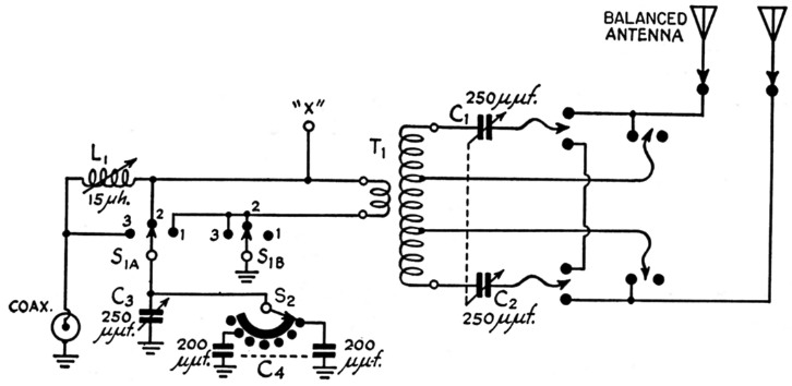
Fig. 1. Complete schematic of the coupler. T1 should be as required for series- or parallel-tuning of the particular antenna-feeder system used (Barker & Williamson type TA antenna coil used in the unit pictured).
| C1,C2 | 250 pF variable, 3000-volt rating (see text). |
| C3 | 250 pF variable, 1000 volt rating. |
| C4 | Nine 200 pF, 1250 volt working, mica condensers. |
| S1 | 2 poles, 3 positions, steatite. |
| S2 | 10 position progressive shorting (Centralab PIS section, steatite). |
The antenna side of the circuit is a more or less conventional plug-and-jack arrangement which may be connected for either series or parallel feed. Fig. 2A shows the plug arrangement for parallel feed, and B for series feed. The taps on the coil are not needed for series feed, but are indicated because the same coil might be used for both series and parallel feed at different times. Dummy jacks are provided for storing the taps.
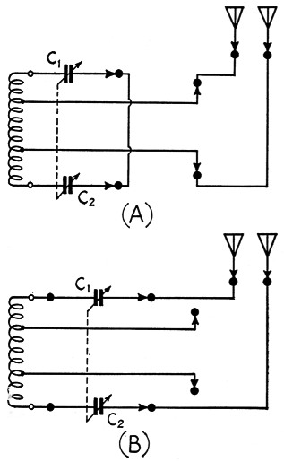
Fig. 2. (A) shows the plug connections for a parallel. tuned antenna-feed line combination. (B) shows the connections for series tuning.
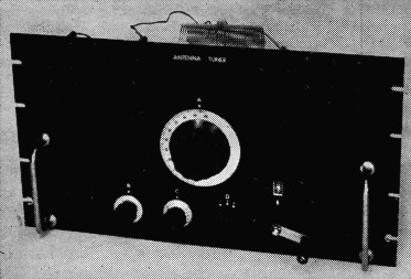
Front view of the coupler. The large center dial controls the antenna tuning capacitors through a right-angle drive. The two knobs at the lower left control the matching-section capacitance, the switch controls the matching-section circuit, and the counter dial drives the matching-secticin variable inductor. All controls have arbitrary letter designations.
The antenna tuning capacitors C1 and C2 have a maximum capacitance of 250 pF each, which is considerably more than is necessary to resonate the 80-meter coil. However, it is sometimes convenient to have the extra capacitance available, as some antennas couple considerable reactance into the tuner which must be canceled out to achieve resonance. As it was expected to use this coupler only on the 80-, 40- and 20-meter bands, no great thought was given to the rather large minimum capacitance of these capacitors. If regular 15 or 10 meter operation is planned it is suggested that 150 or even 100 pF capacitors be substituted. Also, it would probably be wise to make the circuit a little more symmetrical. As may be seen in the back view, one capacitor is much nearer the variable inductor than the other, and has an aluminum support bracket fastened to it.
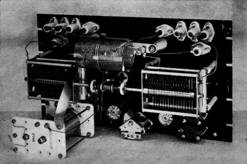
Rear view of the coupler. The antenna feed line comes in from the top. The L-C matching section components are along the bottom. The 80 meter coil is plugged in. A standard 10½ inch aluminum rack panel is used as a mounting base. The output coax connector is behind the variable inductor.
The coax line side of the unit may be set to three different configurations by the circuit switch S1. These are shown in Fig. 3. A shows the switch in position 1, where the fixed link is series tuned. B shows the switch in position 2, with an L-C matching circuit that is useful when the impedance looking into the link is high. C, position 3, is useful when the impedance looking into the link is low.
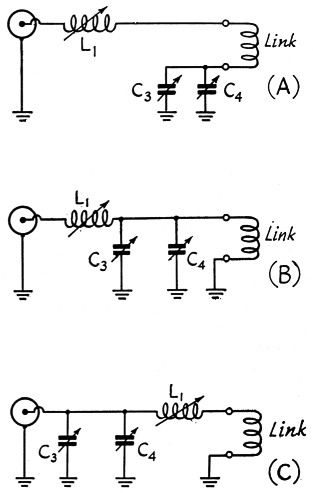
Fig. 3. The three possible matching section circuit arrangements.
(A) shows S1 in position 1,
(B) in position 2, and
(C) in position 3.
Operation
A standing-wave ratio bridge of some kind is an excellent indicator for adjusting the coupler. The controls are simply manipulated to produce a null on the s.w.r. bridge. If one of the "Micromatch" type is used, it may be left in the line continuously. A calibration chart should be prepared which lists the control settings vs. frequency.
The suggested operation of the coupler when it is being calibrated is as follows: Set Sl on position 2, and C3, C4, and L1 on minimum capacitance and inductance, respectively. Plug in the proper coil and adjust the antenna tuning capacitors, C1 and C2, and the coil taps, if used, to give resonance. This would be indicated by a dip on a standing-wave indicator. Then adjust C3, C4 and L1 until the line is matched. Try the other two positions of S1 if necessary. Position 2 of S1 is preferred, as it should give the best harmonic attenuation. Note the similarity of Fig. 3B to a low-pass filter section. It should be possible to match either 52- or 72-ohm coax without difficulty.
The nominal rating of the components used is 500 watts. The major operating precaution is not to operate the circuit switch Si with the power applied. These switches can carry quite a bit more current than they can break. The same precaution applies with somewhat lesser weight to S2 and L1.
The L-C matching section may be used by itself for matching grounded antennas by bringing the antenna line in and tapping into the coupler at the point marked "X" in Fig. 1. No coil should be plugged in the jackbar, and switch Si must be in position 2 or 3. The only precaution is to observe the voltage ratings of the capacitors in the matching section.
If the same type of ceramic stand-offs are used as those in the photographs, be extremely careful when mounting them to the metal panel, as they break very easily. Fiber washers under the nuts and between the ceramic and the panel should help considerably.
T.H. Puckett, W5JXM.