Low-noise receiver design
Reworking a receiver for maximum sensitivity.
This is an interesting article telling how two amateurs were able to improve considerably the performance of a commercial receiver. We think you will be interested in the reasoning and the circuitry involved. However, it should be pointed out that the improvement that can be expected with any receiver will be in proportion to the poorness of its present performance and the lack of outside noise at one's location - you can't expect these changes to help a currently-good receiver or one in a noisy location.
After spending several hundred dollars for a new receiver, most of us feel rather pleased with ourselves - if we didn't, that hollow sensation in the hip pocket would be hard to bear. But how about a few months later, when the novelty has worn off and we've settled down to some serious DX operating? Are there ever any little gnawing doubts? Probably more often than most of us would care to admit. The crux of the situation is that while one receiver may have better selectivity, stability, or operating con venience than another, they are pretty much alike so far as front-end performance is concerned. This is because the industry long ago settled on pentode r.f. amplifiers and pentagrid mixers as the accepted standard. Obviously, two r.f. stages are better than one or none, but manufacturer X's r.f. amplifiers or mixers will have essentially the same noise figure as those of manufacturer Y(1).
As it turns out, low-noise amplifiers have been easiest to build for the v.h.f. bands because of the small frequency coverage (percentagewise) demanded of most v.h.f. receivers. External noise is lowest in the v.h.f. bands, and hence full advantage can be taken of low-noise r.f. amplifiers. Generally accepted theory considers that external noise (static, etc.) is so strong below 25 Mc. that it is useless to use special circuits to reduce internal receiver noise on our general operating frequencies. While this is essentially true, we believe the critical frequency to be more in the order of 10 Mc., indicating low-noise circuits for three of our most important DX bands. This figure of 10 Mc. is somewhat variable, depending on local conditions; certainly the man who lives under a trolley line is little concerned with internal set noise at virtually any frequency.
Testing your receiver
Here is a simple test to determine whether or not a lower noise figure would help your own receiver: set it to or near your favorite DX band (use your regular receiving antenna), tune in a frequency entirely free of any signal, advance the gain until the noise is at a comfortable level, and now substitute a resistor having the same value as the antenna input impedance, usually about 300 ohms. If there was not an appreciable decrease in noise when the antenna was replaced by the resistor, your receiver can stand improvement; most of the noise remaining is being generated within the receiver.
We made the above test on a modified HRO-5, and found that internal set noise masked much of the weak-signal DX. In the course of testing this and other receivers, another interesting fact came to light. Literature covering weak-signal reception, available to us, generally states that the first r.f. stage is the most important since its noise is amplified more than that of any other stage. This apparently does not hold true for the average amateur receiver; a considerable amount of noise is contributed by the pentagrid mixer or converter stage. Further research into the subject disclosed that pentagrid mixer and converter tubes available today have an equivalent noise resistance ranging from 62,000 to 300,000 ohms;(2) in addition, conversion transconductance is low. Economic factors and construction convenience have generally dictated the use of conventional mixers or converters, because they are simple and inexpensive and perform fairly satisfactorily for most medium frequency applications. However, at frequencies above 10 Mc., they may leave quite a bit to be desired.
R.F. amplifiers
The triode is the least noisy vacuum tube amplifier known. A check of tubes narrowed our choice to a triode-connected 6AC7, or the miniature version, the 6AH6, since they have the highest gm and therefore the lowest equivalent noise resistance of available triodes.(3)
A straight triode amplifier is not practical because it will oscillate without neutralization, and neutralization is impractical in multiband receivers. The grounded-grid amplifier overcomes this objection, but in turn has the drawback of heavy input-circuit loading. To overcome this disadvantage, the cathode follower is made to order. The high input impedance of a 6C4 cathode follower stage decreases loading of the tuned circuit, resulting in greatly increased input-signal voltage, and improved r.f. selectivity; while the low output impedance of the cathode follower matches the input of the grounded-grid stage. Our experience has shown the combination to be relatively noise free.
Mixer
Since the grounded-grid amplifier and cathode follower proved so successful, it was decided to try the combination in the mixer stage. Cathode injection looked like a good bet.(4) The circuit was incorporated in the modified HRO-5 and it worked; however, instability, tracking difficulties, and oscillator pulling were quite bad above 7 Mc. This condition was attributed to insufficient frequency separation and the consequent reactance of the local oscillator circuit coupled into the cathode of the mixer, producing sufficient phase shift to cause oscillation in the mixer and pulling of the local oscillator frequency. Again, the 6C4 cathode follower provided a practical solution, by giving necessary isolation, resulting in a cool, smooth-running low-noise mixer. No further difficulty with tracking was encountered.
Circuitry
Fig. 1 shows our low-noise front-end circuit. No a.v.c. should be used on the first r.f. stage. It should be emphasized that in order to utilize the grounded-grid triode mixer it is imperative to use a separate h.f. oscillator. Although a converter circuit may appear complicated, a little study will reveal that it consists of simple triode-oscillator, signal-input and i.f. output circuits. Fig. 2 illustrates modification of two common types of single-tube converters to separate oscillator mixers for use in this low-noise front end. There is nothing tricky about making this modification. One precaution: connect all grounds to the cathode return of the stage being wired. The use of tube shields for all the 6C4s is recommended, especially if they are mounted below deck, as was the case in our receiver. Although major realignment will not be necessary, a touchup of the trimmer capacitors at the high end of each band may be required. Readjust the oscillator trimmers first to bring the receiver back into calibration; then the r.f. and mixer trimmers for maximum gain.
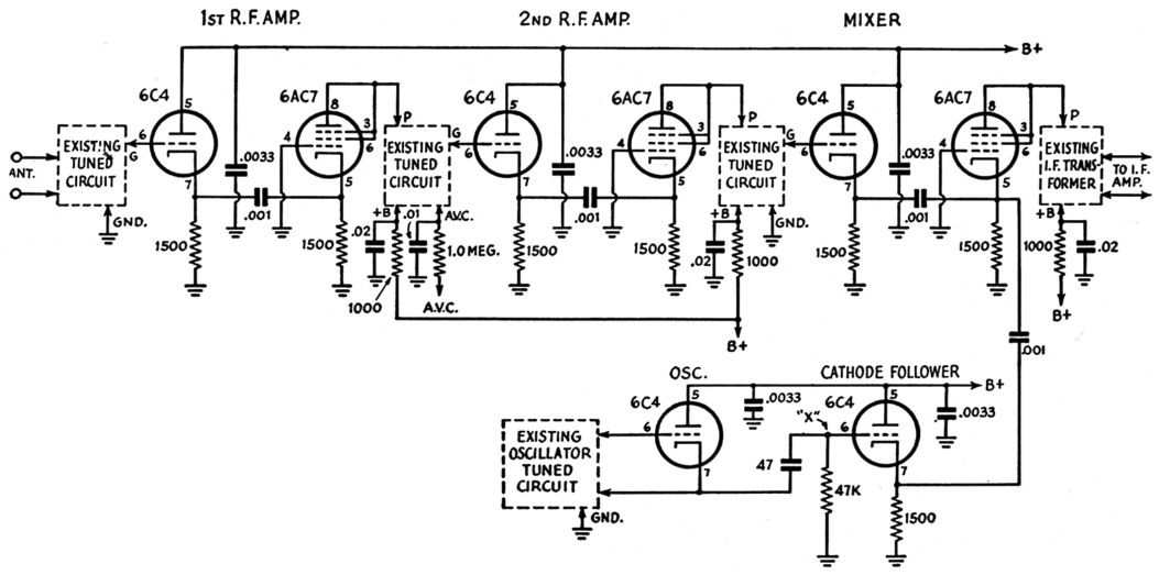
Fig. 1. Circuit diagram of the low-noise receiver "front end," as applied to an HRO.5. The added 6C4s are mounted under the chassis.
All resistors are 3 watt.
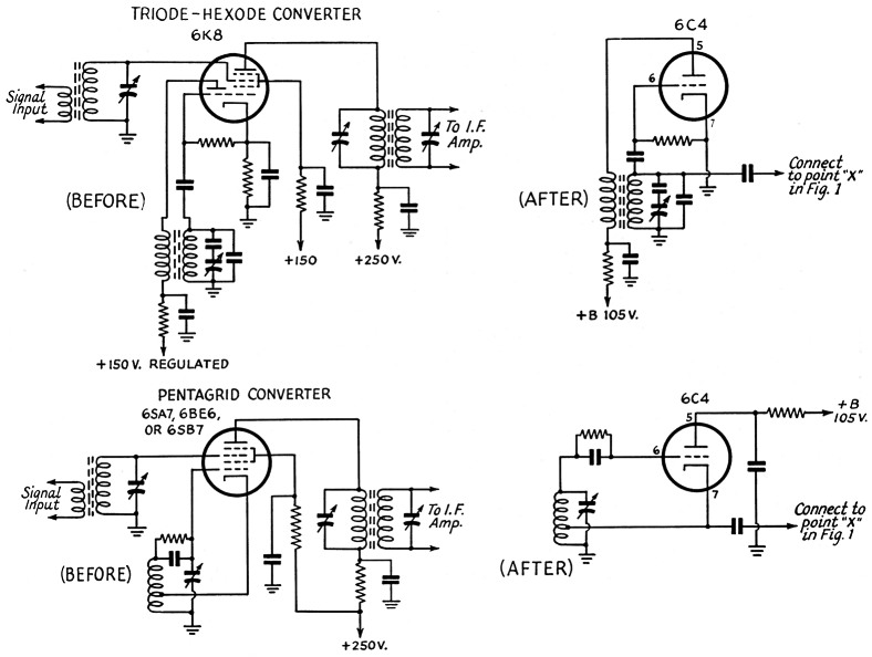
Fig. 2. Typical oscillator circuits, before and after modification.
Conclusion
Here is a circuit that for the first time makes practical the use of low-noise techniques in general-coverage receivers. It is easily applied to any receiver without introducing additional knobs or alterations to existing tuned circuits and, furthermore, works at the first try. The few extra wires and components are well worth the time and expense. Comparative listening tests were made on 14 Mc., between a receiver incorporating this circuit and three late-model stock commercial receivers in the $400.00 class. Listening fatigue attributable to internal noise was considerably less, and twice as many DX stations were heard.
Notes
- Two r.f. stages are not necessarily better than one. If a low-noise mixer is used, one good r.f. stage should be sufficient, and it would lessen the chances of cross-modulation in the front end.
- Radiotron Designer's Handbook, 4th Edition, page 938.
- The more elements there are in a vacuum tube, the greater the noise that is produced, because of the random division of the cathode current between the elements. See Terman, Radio Engineer's Handbook, page 294.
- Goodman, "Some notes on improving small receiver performance," QST, December, 1953.
Harry Longeriche, W2GQY/4
Robert D. Smith, W5LHD.