The multimatch antenna system
Unique design providing essentially constant impedance over several bands.
For a long time, hams have been searching for a single antenna that could be fed efficiently with a low-impedance transmission line on several bands. At last a simple but ingenious design by W3DZZ provides a solution. He has applied some well-known but neglected principles to both wire and parasitic-beam antennas.
Radio transmitters and receivers have en-joyed rapid development in flexibility to the point where changing bands is a matter of only spinning a dial or two and flipping a couple of switches. In contrast, the operation of a single antenna on several bands is usually done only at the expense of high standing waves on the feed line, because of the wide variation in antenna feed-point impedance from band to band.
Some work done by the author several years ago in connection with a dual-band parasitic array(1) has led to the development of a simple wire antenna covering five bands, from 80 to 10 meters. This antenna can be fed with a low-impedance transmission line without incurring excessive s.w.r. on any of these bands.
Basic design
The fundamental principle of the system can be explained with the aid of Fig. 1. In Fig. 1A, sections h1 constitute a half-wave dipole for some frequency f1. This dipole is terminated in lumped-constant trap circuits resonant at f1. Additional wire sections, h2, extend beyond the traps. If the system is excited at frequency f1, the traps serve to isolate the dipole much as though insulators were inserted at these points.(2)
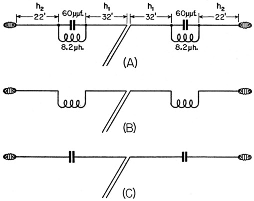
Fig. 1. Sketch illustrating the three fundamental modes of the multimatch antenna.
At frequencies much lower than f1, the traps no longer isolate the dipole, but act simply as loading inductances in a second dipole whose electrical length is made up of 14, h2 and the inductive reactance of the traps, as in Fig. 1B.
At frequencies much higher than f1, the traps again cease to isolate the sections, the traps now acting as series capacitances, as in Fig. 1C.
Another important consideration in this multiband system is that low impedance at the center feed point of the antenna occurs not only at its fundamental resonance but also at any odd harmonic of the fundamental.
By applying these principles, and by proper selection of the values of L and C in the traps, and choice of lengths for hl and h2, it has been possible to arrive at a design where the system operates as follows:
- Sections h1 form a half-wave dipole resonant in the 40-meter band. The traps, resonant at the same frequency, isolate this dipole from the outer sections.
- The inductive reactance of the traps is such that the entire system, including sections h2, resonates as a loaded half-wave dipole for the 80-meter band.
- The capacitive reactance of the traps at higher frequencies is such that the entire system resonates as a 3/2 wavelength antenna on 20, 5/2 wavelength on 15, and 7/2 wavelength on 10 meters.
The antenna is fed with 75-ohm Twin-Lead, and Fig. 2 shows the results of s.w.r. measuremente made across each band. Proper dimensions are given in Fig. 1A.
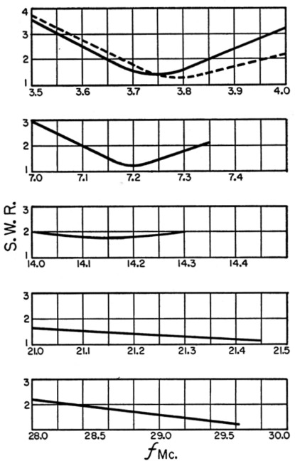
Fig. 2. S.w.r. measurements made on the antenna of Fig. 1A. The dashed lines show measurements made on a 122-foot dipole in the same location for comparison.
Trap construction
The values of C and L used in the traps are quite critical. The capacitance should first be adjusted accurately to 60 pF, then the inductance should be trimmed until the trap resonates at 7200 kc. This should be done before the traps are inserted in the antenna. The inductance will be approximately 8.2 µH. The traps made by the author are 6 inches long and weigh only 6 ounces and the Q is well over 100. They will withstand the voltage developed by a 1-kw. transmitter. Samples are shown in the photograph. The wire-antenna capacitor is made up of concentric lengths of 1-inch and 3%-inch aluminum tubing separated by polystyrene tubing with -inch walls, molded around the inner conductor. The polystyrene is also flowed into a series of holes in one end of the outer conductor so that the strain of the antenna will not pull the assembly apart. The inductor is wound with No. 14 wire and is concentric with the capacitor. The inductor is weatherproofed by molding it in insulating material. Other construction might be used, of course. As an example, a conventional inductor and capacitor could be enclosed in a plastic box, suspended across an insulator. This would, however, add to the weight.
A three-band parasitic beam
The principle of isolating sections of an antenna with resonant traps has been applied to a parasitic beam antenna that operates on 10, 15 and 20 meters. This array with dimensions is sketched in Fig. 3. The array is a five-element job on 10 meters, with two reflectors spaced approximately 0.15 wavelength, and two directors spaced approximately 0.2 wavelength. On the other two bands, three elements are active. On 15 meters, spacings are approximately 0.22 wavelength for the reflector and 0.29 for the director. On 20 meters, the approximate spacings are 0.14 and 0.2, respectively.
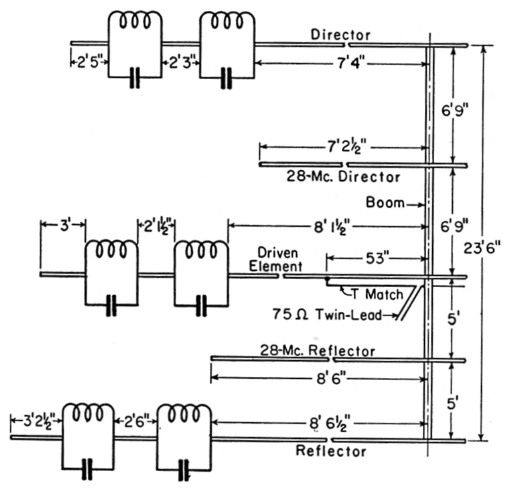
Fig. 3. Dimensions of the 3-band parasitic beam found optimum at W3DZZ. Dimensions are, of course, duplicated on the opposite side of the boom.
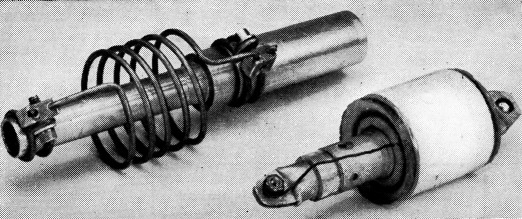
Lightweight weatherproof traps made by the author. To the left is the type inserted in beam elements, while the other one is suitable for wire antennas.
Fig. 4 shows a breakdown of a suggested method of construction of the three main elements. Each element starts out with a 12-foot center section to which various sections are added at each end. Provision is made for adjusting the length from the center of the element to the first (28 Mc.) trap, the length between traps, and the section on the outside of the second (21-Mc.) trap. The photograph shows an example of the array traps used by the author. Here, again, the capacitor is made up of concentric aluminum or durai tubing separated with polystyrene, and the coil is concentric. In each capacitor, the polystyrene insert (Fig. 4) should provide a tight fit to both sections of tubing, and the insert should be driven into the outer conductor to the shoulder. The inner conductor should be driven into the insert for a distance of 2¾ inches (thus protruding 2 inches inside the outer conductor). This gives a capacitance of approximately 25 pF. The trap inductors are wound with No. 8 wire. The 10-meter inductors have 5 turns 2½ inches in diameter, with the turns spiced approximately ½ inch. The 21 Mc. inductors are similar, but have 7 turns. As with the wire-antenna traps, the inductors should be adjusted for resonance near the center of each band before they are installed. The ends of the inductors are wound around the element sections and fastened with clamps. The array is fed with a T match to 75-ohm Twin Lead.
Fig. 4. Breakdown of the element assembly. Sections A and B are assembled permanently. Other sections may be telescoping for adjustment. Detail of the polystyrene inserts is at the right. The 7/8 inch o.d. sections should be inserted to a depth of 2¾ inches.
Fig. 3 shows the element dimensions used by the author. Antennas of this type, in both wire and beam forms, have been installed by many amateurs, using traps constructed by the author. Without exception, all have been enthusiastic about the performance.
Notes
- Buchanan, "Duo-band ham antenna," Radio & television news, december, 1950.
- Morgan, "A multifrequency tuned antenna system," Electronics, August, 1940.
Chester L. Buchanan, W3DZZ.