Unidirectional loops for transmitter hunting
Less guesswork in mobile d.f. work.
This article not only describes the construction and use of a d.f. loop that eliminates much of the uncertainty in making "fixes" in fox hunts, but it also contains some interesting observations regarding the conducting of this highly popular activity.
Mobil hams in the Wichita area have been E running 10 meter hidden-transmitter hunts each week for the past three years or more. Not long after these hunts were inaugurated, it became evident that the affairs were rapidly degenerating into rat races. Under the usual rules, where the first car to arrive at the site of the transmitter was declared the winner, the honor system for compliance with existing speed limits failed completely. It became obvious that the contests would have to be conducted along different lines, if they were to be continued on a safe and sane basis. In the interest of public safety, we felt that we could not continue to encourage speedy and hazardous driving. We realized too that our call license plates and long whip antennas could easily draw attention to us in any adverse publicity.
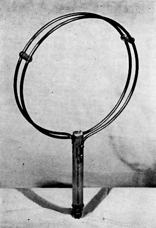
The unidirectional 10 meter d.f. loop is a simple affair, consisting of two turns of copper tubing mounted on an insulating rod. Directivity is adjusted by the trimmer condenser at the center.
For some time now, we have been operating under a scheme in which precision and skill are substituted for speed and recklessness. The time element has been eliminated entirely, and all hunts are now based on the mileage covered between a common starting point for all cars and the hidden transmitter. Speedometer readings are recorded at the starting point, and again when the car reaches the objective. There is no time limit, and the winner is the one who reaches the hidden-transmitter site over the shortest route.
The changes in rules naturally have brought about a search for more accurate direction-finding gear, rather than speedier cars. Perhaps the most important result has been the adoption of a unidirectional loop antenna by the hunters. It has eliminated the possibility of starting out in exactly the opposite direction, and reduced the probability of overshooting the transmitter. In eliminating the necessity for triangulation, it has simplified the hunting technique, and placed it more within the grasp of the YL and Jr. Ops.
The unidirectional loop antenna works on rather well-known principles. In simple terms, a loop that is not accurately balanced in respect to ground will exhibit two modes of operation. One mode is that of a true loop, while the other is that of an essentially nondirectional vertical antenna of small dimensions. The voltages introduced by the two modes are out of phase, and will add or subtract, depending upon the direction from which the wave is arriving.
The theoretical true loop pattern is illustrated in Fig. 1A. When the voltage introduced by the antenna mode is large, the nondirectional pattern of the vertical-antenna mode predominates, and the loop will show little directivity, as shown in Fig. 1B. When the antenna effect is small, one of the loop lobes will be reduced, while the other will be correspondingly enlarged (see Fig. 1C). When the voltages introduced by the two modes are equal and 90 degrees out of phase, one of the lobes will be canceled out, making the loop unidirectional, as indicated in the pattern of Fig. 1D.
Since the loop pick-up will usually be predominant, when the dimensions of the loop are small in terms of wavelength, the loop and antenna effects can be balanced by detuning the loop so as to reduce its pick-up to equal that introduced by the antenna effect.
The loop shown in the photograph consists of two turns of finch copper tubing, 11 inches in diameter. The two ends are flattened out, and fastened to opposite sides of a 1 inch diameter insulating rod that serves as a mounting. The center of the loop is broken, and a 20 pF. mica trimmer is inserted in series. The ends of the tubing at the break are supported in a slot cut in the end of the insulating rod. The rod of the loop shown in the photograph is a piece of 1-inch polystyrene. However, a piece of ordinary broomstick will provide adequate insulation.
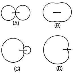
Fig. 1. Small-loop field patterns with varying amounts of "antenna" effect. The heavy lines show the plane of the loop.
The loop is connected to the receiver input with a length of coax cable. After the receiver has been tuned to the desired operating frequency, the trimmer condenser in the loop should be adjusted for maximum background noise. If no peak in noise can be found, the condenser range value should be changed. An 11-inch loop should require no more than 5 to 15 pF.
Once a noise peak has been established, a signal and the receiver S-meter should be employed. (If the mobile receiver is not equipped with an S-meter, the circuit of Fig. 2 can be added.) The capacity of the loop condenser should then be carefully reduced until the loop acquires a unidirectional characteristic. The final setting of the trimmer condenser depends upon the front-to-back ratio desired. Complete cancellation of signals from the back can be acquired at the expense of a certain amount of frontal signal pick-up.
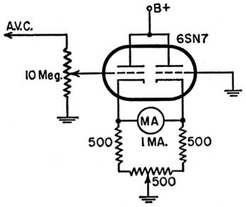
Fig. 2. S-meter circuit widely used in transmitter hunting.
This type of loop is, of course, oriented for maximum signal in contrast to a conventional d.f. loop which is usually worked on the signal null. In the use of the loop, it will be found that resonant antennas or other objects are highly capable of receiving signal energy and reradiating it. The possibility of the loop receiving reflected signals from the mobile whip should be thoroughly investigated. Usually, the loop when used on one side of the car will be more susceptible to whip reflections than it will be on the other. This depends upon the car body contour and the distance between the loop and the whip. In some installations, it may be necessary to pull the whip down while taking loop bearings.
In the process of hunting, it is advantageous to keep the hidden transmitter on the loop side of the car. The maximum-to-minimum signal, and the exact direction, will be less pronounced if the loop has to look across a reflecting or diffusing car roof. Whenever the loop is used in the vicinity of a strong signal, some means of attenuating the antenna circuit should be used, rather than to decrease the S-meter sensitivity. Various resistor values, switched in parallel with the antenna input, will achieve this.
Those who organize, or participate in, this popular activity will find that many headaches will be avoided if the rules place strong restriction against hunting or hiding on private property. We have also found it highly advisable to notify the local police in advance of a scheduled hunt. Summer-night hunts, with dozens of dangling loops and seeking searchlights, can load the police telephone circuits with curious inquiries!
Warren U. Amfahr, W0WLR.