Using the 6360 dual tetrode on 220 Mc.
Low-cost all-tetrode transmitter for the 220 Mc. beginner.
Unless one is content to get along with the various receiving tubes that can be pressed into transmitter service, firing up on 220 Mc. can be a rather expensive proposition. The 832A, surplus variety, has been the only tube that would do the job at power levels above the receiving tubes, without setting the purchaser back a sizable piece of change. And now, unless you already have your 832s, they are no longer very attractive from the standpoint of price. Other tubes usable at 220 Mc. begin at around $15.00, and range on up from there.
The 6360, a small dual tetrode introduced recently by Amperex, makes the 220 Mc. picture a little brighter. It won't handle quite as much power as its larger brothers, the 6252 and 5894A, but it works well on 220 Mc. and it sells at a receiving-tube price. The tube's low cost is largely the result of its single-ended construction. All connections are brought out through the base, so it can be made on the same machinery that grinds out receiving tubes.
Actually, the 6360 is built a good deal like an oversized 6J6, with screens added. A central heater and cathode have pairs of other elements on either side. Compact construction and short leads result in a tube that works well on 220 Mc., and will even go to 420, in a pinch. One 6360, tripling, will drive another as a straight-through amplifier on 220 Mc., and that is how the tubes are used here.
Transmitter circuit
Circuitwise, the rig described here is a departure from the technique we have used in most v.h.f. transmitters described recently, in that a conventional tetrode crystal oscillator is used, rather than a triode in an overtone oscillator. This switch was made mainly for the sake of variety, to show newcomers that there are oscillators other than the overtone types used so often in recent years. The tetrode oscillator has an advantage, too: you can put in 8- or 12-Mc. crystals interchangeably. The oscillator plate circuit may be tuned to 24 Mc. or 36 Mc. if 12-Mc. crystals are used, allowing a choice of doubling or tripling in the second stage.
The oscillator is a 6CL6, as is the first multiplier. Type 5763s could probably be substituted in these stages, or a single 6360 can be used for both, if you want to standardize on one tube type. A balanced plate circuit is used in the multiplier, so that its output can be capacitively coupled to the 6360 tripler grids. We insert a hint at this point: If you run into trouble with insufficient grid drive to the 6360 tripler, try putting a small plastic trimmer between the low side of L2 and ground, to balance up the capacitances on either side. It was not needed in the original, but it would be well to remember the suggestion, just in case.
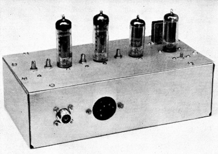
The 220-Mc. tetrode transmitter. At the right are the 6CL6 crystal oscillator and multiplier stages, with the 6360 tripler and amplifier in the center and left, respectively. The rig is built on a sheet of aluminum which is screwed to an inverted chassis.
The 6360 push-pull tripler to 220 Mc. is inductively coupled to the push-pull final stage. No neutralization is shown in Fig. 1. Should neutralization be needed, a method for achieving it is given later. Output from the final 6360 plate circuit is taken off through coax, and provision is made for tuning out the reactance of the link, with C4.
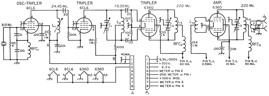
Fig. 1. Schematic diagram and parts information for the 220 Mc. tetrode transmitter.
Resistors are half watt unless otherwise specified.
Capacitor values below 0.001 are in pF; all ceramic.
| C1 | 11 pF miniature butterfly variable (Johnson 11MB11). |
| C2,C3 | 5 pF miniature butterfly variable (Johnson 5MB11). |
| C4 | 15 pF miniature (Johnson 15M11). |
| L1 | 14 turns No. 28 enam. on 3/8 inch iron-slug form (National XR-91). |
| L2 | 7 turns No. 20, ½ inch diam., 7/16 inch long, center-tapped (B & W Miniductor No. 3003). |
| L3,L5 | 4 turns No. 18 enam., 5/16 inch diam., center-tapped. Space twice diameter of wire, except for 1/8 inch space at center. |
| L4 | 2 turns same as L3, center-tapped. Adjust turns spacing and degree of coupling to L3 for maximum grid current. |
| L6 | 2 turns same as L5, close-wound. Adjust position at center of L5 for maximum output. |
| J1 | 8-pin male chassis fitting (Amphenol 86-RCP8). |
| J2 | Coaxial fitting, female (Amphenol 83-1R). |
| P1 | 8 contact power cable connector, female (Amphenol 78-RS8). |
| RFC1 | 750 µH r.f. choke (National R-33). |
| RFC2,RFC3 | 17 turns No. 28 enam. on high value 1 watt resistor, or use Ohmite Z-235. |
Construction
The transmitter is built on a flat plate of sheet aluminum 5 by 10 inches in size. This is screwed to a standard aluminum chassis of the same dimensions, that serves as both case and shielding. If more complete shielding is required, a perforated metal cover may be made to go over the top, as was done with the 6- and 2-meter rigs described in October, 1954, QST. All parts except the power and coaxial output connectors are mounted on the top plate. The two connectors mount in holes in the rear wall of the chassis. The mounting screws are held in place on the fittings with nuts and other nuts on the outside of the chassis hold the fittings in position.
The tube sockets are along the centerline of the plate, two inches center to center, with the oscillator socket 1_3/8 inch in from the right end, as seen in the photographs. The crystal socket and the oscillator plate coil, L1, may be seen at the lower and upper right, respectively, in the bottom view. The tripler plate tuning capacitors are midway between their respective sockets.
Except for the power leads, there is no "wiring" in the usual sense, as all r.f. leads should be extremely short. The decoupling resistors and r.f. chokes in the various power circuits are supported on tie points. Three single-lug strips and two double-lug ones are needed. All the power wiring is done with shielded wire, as an aid to TVI prevention. The coils L2, L3 and L4 are soldered directly to the stator support bars of their trimmers, with the shortest possible leads.
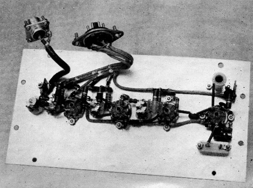
Lifting the top plate of the 220-Mc. transmitter, in the position shown in the other photograph, the underside shows all the parts except the tubes and crystal. Note the method of attaching the power and coaxial fittings. Nuts hold their mounting screws in place, so that they can be fastened to the rear wall of the chassis.
Adjustment
The power supply for testing the transmitter should deliver at least 3 amperes at 6.3 volts, a.c. or d.c., and 200 to 300 volts d.c., at 200 ma. The lower voltage is plenty for the test work, though up to 300 may be used when everything is properly adjusted. If a 300-volt supply is used for the testing, the tubes can be protected from excessive drain by connecting a 5000-ohm 10-watt resistor in series with the power supply lead. The power connectors, Jl and P1, make provision for metering all plate circuits except those of the oscillator and first tripler. The power leads to these are shown connected together, to Pin 2 of J1, but during testing they should be fed separately through a milliammeter, as described below.
Testing will be easier if a receiver capable of tuning to 8 and 24 Mc. is available. Connect a 0-50 or 0-100 milliammeter between Pin 2 of J1 and the oscillator plate-screen circuit, at the low side of the 22,000-ohm screen-dropping resistor, point A on the schematic. Be sure that the tripler plate and screen resistors are disconnected for the time being, to prevent this stage from drawing current. Apply 200 to 300 volts d.c. through Pin 2 of P1, and tune the plate circuit of the oscillator to the third harmonic of the crystal frequency. If you can listen on this frequency (24.45 to 25 Mc., depending on choice of crystal) a large increase in signal strength should be noted as the coil is tuned through resonance. A double check on frequency with a calibrated grid-dip or absorption wavemeter is recommended. Oscillator plate-screen current will be about 20 mA.
Now connect the oscillator plate-screen power lead directly to Pin 2 on J1, and insert the meter in the lead to the tripler plate-screen circuit, point B on the diagram. Apply voltage and tune the tripler plate circuit for maximum output at 73.35 to 75 Mc. A 2 volt 60 mA pilot lamp with a single-turn loop of insulated wire, about a half inch in diameter, may be coupled to L2 to serve as an output indicator. The 6CL6 tripler plate-screen current will be about the same as the oscillator, around 20 mA at 300 volts.
Now wire the power leads to these two stages as shown in the diagram. Leave the 300-volt lead connected to Pin 2 of P1, and connect a 100 mA meter between Pins 2 and 4, to measure the 6360 tripler plate-screen current. A low-range milliammeter, about 0-10 mA, should be connected between Pin 5 and Pin 1, to measure final grid current. Tune C2 for maximum indication on this meter. With no plate voltage on the final stage, there should be at least 3 ma. grid current. Adjust the spacing between L3 and L4 carefully, retuning C2 after each adjustment, for maximum grid current.
In adjusting the final stage, we will ignore the eventual use of a modulator, and connect our power supply direct to the final stage temporarily. Information on modulation will be given later. Solder a jumper between Pins 2 and 4 on J1, so that voltage will be supplied to the 6360 tripler. Connect a temporary jumper between Pin 2 and Pin 7, to feed voltage to the final screen, and connect the 0-100 milliammeter between Pins 2 and 8, to measure final plate current. A 10- or 15-watt light bulb may be used as a temporary dummy load, connected to J2. Apply voltage and tune C3 for minimum plate current, or for maximum output as indicated in the lamp load. Adjust C4 for best output. The setting of C4 and the degree of coupling between L5 and L4 will be different for an antenna, however, as the lamp is not a good load at this frequency.
If the stage is completely stable, maximum output, maximum grid current and minimum plate current should all occur at the same setting of the plate tuning capacitor, C3. Another check for neutralization is to cut the drive for a brief period by removing plate and screen voltage from the tripler. Grid current should drop to zero when this is done. If it does not, the final stage is oscillating, and must be neutralized. In the original model, there was no actual self oscillation, but the stage was not completely stable until a small amount of neutralization was added.
This is done very simply with the 6360. The leads are so arranged within the tube that all that is required for neutralization is a very small capacitance between Pins 3 and 6, and between Pins 1 and 8. A stub of No. 18 wire about % inch long is soldered to Pin 6, with its opposite end "looking" at Pin 3. A similar stub is soldered to Pin 8, with its free end adjacent to Pin 1. The ends can then be bent toward or away from the grid pins to give the required capacitance.
Putting the rig on the air
When all stages have been adjusted correctly, the plate voltage may be increased to 300 on all stages, if you want to run the maximum power of which the tubes are capable. Current drains indicated on the schematic diagram are for 300-volt operation. Staying at 250 volts or less allows more conservative operation, and may be well worth while, in the interest of longer life for the 6360s. There is no great advantage to be gained from pushing the tubes excessively, as doubling the power output will net less than one S unit improvement in signal level at the receiving end.
In feeding power to an antenna system using coaxial line, it is merely necessary to connect the coax to the output fitting, J2, and adjust the coupling and C4 for maximum radiated power. A field-strength meter that will be helpful in this was described in QST for December, 1953, page 43. If 300 ohm Twin-Lead or open-wire line is used to feed the antenna, coupling to the transmitter is done with a coaxial balun, made as shown in Fig. 2. The balun may also be used at the antenna end of the coax, if the antenna system is designed for 300 ohm balanced lines. The part of the balun that plugs into the transmitter can be of any convenient length.
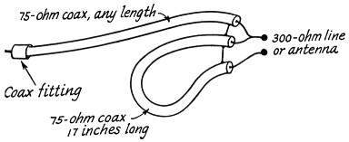
Fig. 2. Coaxial line balun for feeding balanced loads from the 220-Mc. transmitter.
To modulate the transmitter, the final plate and screen are fed through the secondary of the modulator output transformer, as shown achematically in Fig. 3. The circuit is shown in basic form in the interest of simplicity. The actual connections for the power leads should be as shown in the main diagram, Fig. 1. The modulated plate voltage is brought in to Pin 6 on Pl. A screen-current meter, or a jumper, should he connected between Pins 6 and 7, and a plate meter or jumper between Pins 6 and 8.
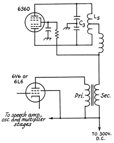
Fig. 3. Simplified diagram showing how a modulator is connected to the final stage.
A modulator of simple design that can be adapted readily to use with this transmitter was shown in QST for December, 1954, page 29. A 6L6 can be substituted for the 6V6GT shown in the original, if more audio power is required.
Power output at 300 volts is about 10 watts, which is enough to do interesting work on 220 Mc. if a good antenna system is used. Antenna ideas can be found in December, 1953, QST, or in any recent edition of either The Radio Amateur's Handbook, or the ARRL Antenna Book. The transmitter may also be used as a source of driving power for any of the larger dual tetrodes, such as the 6524, 6252, 5894 or 9903. The first two will take up to 50 watts input on 220 Mc., the latter two up to 100 watts or more.
Edward P. Tilton, W1HDQ
Mason P. Southworth, W1VLH.