Ferroxcube cores and a high-selectivity I.F. amplifier
Design notes and suggestions for improved receiver selectivity.
If you follow receiver design and improvements, you will be interested in this account of a new inductor-core material that can be easily used by the amateur. Several possible circuits are described, as well as the practical design data for a high-selectivity 20-kc. i.f. amplifier.
Within the last few years there has been considerable interest in the development of the ideal communications receiver. The progress made toward this goal can be readily seen if one traces the development of commercial communications receivers during the past nine years.
The trend in receiver design has advanced from the simple but effective regenerative i.f. amplifier (single-signal superhets so popular in the prewar ARRL Handbooks) to the complicated triple-tuned and quadruple-tuned low-frequency i.f. amplifier of the present day. The mechanical filter (or magnetostriction filter) has recently been developed, and it provides an opportunity to obtain a maximum skirt selectivity and quite narrow bandwidths with a minimum number of stages. And, of course, we still have our old stand-by, the crystal filter. However, very high-Q selective LC filters can be designed that will provide a maximum receiver selectivity and which can be easily constructed by the amateur radio designer.
Several excellent articles have appeared in QST on selective amplifiers.(1),(2),(3) The purpose of this article is to collect together some practical data, which the author has accumulated during the last few years of experimental receiver design, and to present these data in the form of notes for the amateur who prefers to build his own receiver. And, together with some simple circuit theory, an amplifier will be designed that has an extremely narrow bandwidth and excellent skirt selectivity. In conjunction with a good r.f. tuner, this amplifier will outperform any receiver which is at present commercially available. The recent advances made in the development of low-loss ferromagnetic-cored materials for high-Q inductors have made coil design and construction a pleasure, and they inspired the author to write this article. Since the heart of the amplifier is the highly-selective filter, it is necessary that a good portion of this article should be devoted to a general introduction to the use of these core materials.
General considerations
In the design of a communications receiver for radiotelegraphy, it is the author's opinion that a good receiver should be a double-conversion superhet and that the second i.f. should be as low as possible, in order to achieve the required selectivity and stability. Low-frequency amplifiers can readily be designed that have noise figures near to unity but, in any case, the over-all noise figure of the receiver is decided in the first stages, so this factor will not be considered here. Two stages of 455 kc. amplification should be provided to avoid image problems with the low second i.f. The 455 kc. signal should be fed to the second mixer at low level by means of a cathode follower. The signal-handling capacity of the stages before the narrow-bandwidth stages should have sufficient dynamic range to avoid cross-modulation distortion by strong adjacent-channel signals.
Operators not used to copying signals received through a very narrow bandwidth will find that this new experience requires some learning. The familiar ring of a keyed signal, so characteristic of a very selective crystal filter, is considerably reduced by the use of very selective bandpass coupled circuits. Hence, narrower bandwidths, for the same degree of ring, can be used. These circuits are in general designed to produce an optimum flat-top amplitude response. For signaling speeds of 20 w.p.m. and less, the keyed signal sounds clear and with little ring in a 30-cycle bandwidth, except under conditions of great interference of an impulse nature as, for example, local thunderstorm conditions. As the bandwidth is reduced below 20 cycles, the Morse characters start to run together and the information capacity of the channel approaches zero, as the bandwidth approaches zero. (The power required to transmit reliably a given rate of information approaches infinity.)
In the circuit design to follow, an amplifier bandwidth of 100 cycles is chosen because this bandwidth is easily obtained with presently-available circuit components. Additional narrow-band audio-frequency filters can be used if necessary after the signal is tuned in. The over-all circuit stability (from transmitter to receiver) required for operation with a 100-cycle filter is such as to require fine vernier action for the h.f. oscillator control, in order to "hold" the signal in the passband.
Ferroxcube pot cores
If an air-wound coil is placed in a medium of permeability µ times that of air, the sell-inductance L will also be increased µ times. Since the copper losses remain constant, the Q of the inductor will be increased. The resultant increase of the quality factor will depend on the additional losses introduced into the coil by the core. These losses may comprise eddy-current losses, hysteresis losses, and residual core losses. Recently, great advances have been made by manufacturers in producing ferromagnetic materials which introduce very small losses. Ferroxcube III is a low-loss manganese-zinc ferrite with a cubic crystal structure. The metal oxides are extruded in the form of a plastic mass and fired at a high temperature; the result is a material of extremely high resistivity and having mechanical properties which resemble porcelain. This material has many uses and is formed into quite a variety of component shapes. The "pot core" is a specially-designed form developed for very high-Q coils as used in bandpass filters in carrier telephony and i.f. coils in radio engineering. As shown in Fig. 1, the pot core(4) consists of a ring, two disks, and a slug. The slug is slightly shorter than the ring, leaving an air gap in the otherwise closed magnetic circuit. The copper windings are wound on a small plastic bobbin. Since the turns are entirely surrounded by a material of high permeability, excellent shielding is provided, and coils can be placed quite close together without causing undesired coupling. The pot-core assembly can be bolted directly to the metal chassis without affecting the Q. The effective inductance is slightly increased by grounding the core, since the distributed capacity effects are changed. However, this is only of the order of a few pF. The upper frequency limit for Ferroxcube tuned inductors is about 500 kc.
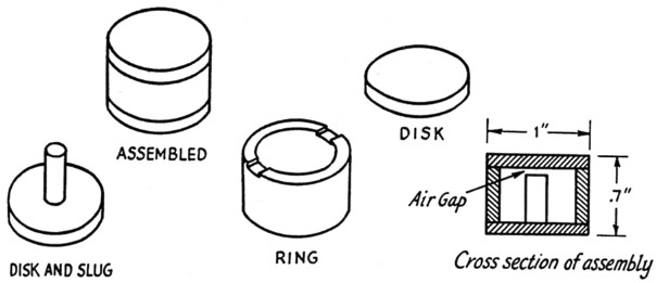
Fig. 1. Component parts and assembled pot core (Ferroxcube D-25/17,5).
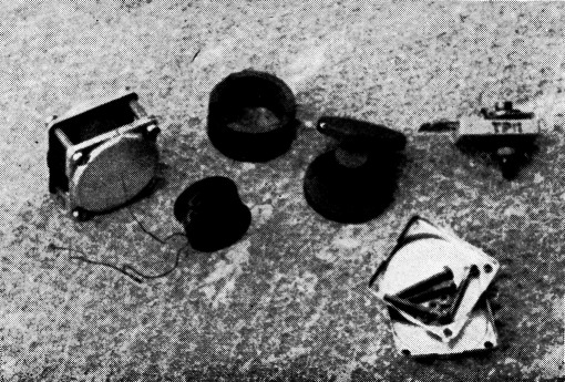
Ferroxcube pot cores make it possible to build high-Q inductors for "super-selective" i.f. amplifiers. The component parts and a complete assembly are shown here.
Application of pot cores
If the tuned filter is to be used as the load impedance of a tuned amplifier, some special considerations are necessary in order to insure maximum stability for the inductance. With Ferroxcube, the permeability decreases (i.e., the inductance decreases) as a result of d.c. flowing through the windings and causing premagnetization of the core material. Another factor to consider is the low saturation properties of Ferroxcube. Therefore, if the sharply-tuned filter coil is included directly in the anode circuit of the output valves of the amplifier, where the anode current is likely to change with the signal voltage, the effect is to detune the filter and increase the bandwidth. The simplest method of reducing these effects is to tap the plate quite a way down on the inductor, so that the d.c. current flows through only a few turns of the coil. This results in additional advantages, since it reduces loading of the tuned circuit by the plate resistance of the valve, and provides a convenient means of reducing the stage gain. (The stage gain can become rather too high as a result of the large inductance values needed to tune to low frequencies with convenient sizes of tuning capacitors.)
The other important consideration for a coil wound on a magnetic core is the temperature coefficient of the core material. Because of the low Curie point (the temperature at which the permeability becomes practically unity) of Ferroxcube materials, the permeability of the material is quite temperature-sensitive. Since the inductance varies directly with the permeability. its temperature coefficient will be identical with that of the core. This temperature coefficient can be inadmissably high for coils used in narrow-band sharply-tuned filters. The influence of the core material on the inductance must be decreased, and this is achieved by providing an air gap. In general, there is an optimum air-gap size for a given Q. In some cases, especially at low frequencies, it is desirable to choose an air gap larger than optimum for a given Q, in order to increase the stability of the coil. A larger air gap also reduces premagnetization effects. Therefore, the largest air gap for the given Q should always be used. As a general rule, the higher the frequency the greater the optimum size of the gap. For gaps larger than 0.5 mm. the core should be symmetrically located, leaving half the total tap at each end.
For frequencies less than about 30 kc. the best Q is obtained by winding the coil with solid enamel-covered wire (not silk-covered), with the wire size chosen to fill the available winding space for the particular value of inductance required. For frequencies above 30 kc., and most certainly for frequencies between 100 and 500 kc., the best Q is obtained by using Litz wire. The number of turns required depends on the length of the air gap, since the effective permeability is a function of the air-gap size. For a given pot core and a given gap size,
![]()
where:
L = inductance, mH
N = number of turns.
The factor ![]() is quoted by the material manufacturer, and inductors wound with the number of turns specified are generally within a few per cent of that required.
is quoted by the material manufacturer, and inductors wound with the number of turns specified are generally within a few per cent of that required.
Circuit design notes
Narrow bandpass filters will be discussed briefly in this section. In amplifier design the desired parameters are stage gain at resonance, selectivity, and off-channel response. The stage gain should be kept low, to avoid trouble with oscillations caused by the difficulty of decoupling the stages at low i.f. frequencies. Single-tuned circuits are not recommended for use in the i.f. amplifier because they give a comparatively narrow passband and poor attenuation outside the passband (a crystal is a very high-Q simple circuit). Capacitance or inductance coupling between two tuned circuits may be used to give a bandpass selectivity curve with good-attenuation outside the passband. The coupling impedance may be in shunt connection, the so-called common coupling, or it may be in series, the so-called top-end coupling. Four common types are illustrated in Fig. 2.
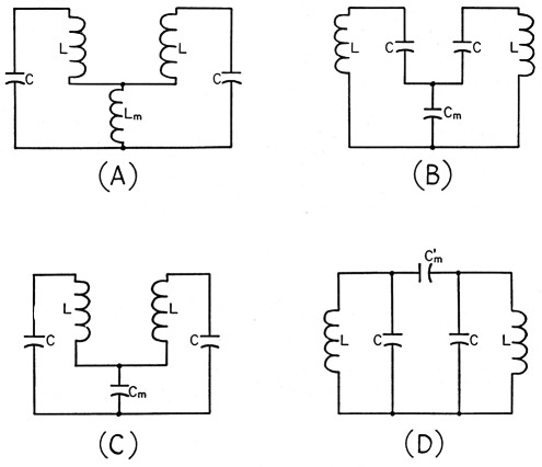
Fig. 2. Four common types of coupled circuits. A, B and C illustrate shunt coupling, and D is a form of series coupling.
All of the methods of coupling shown in Fig. 2 give somewhat similar selectivity response curves near resonance (for near-to-critical coupling). The common inductance type, Fig. 2A, is superior for coupling that is slightly greater than critical, since both peak frequencies (of the double-humped response curve characteristic of overcoupled circuits) move away from the mid-frequency as Lm is increased. The response of this circuit is similar to that for a double-tuned inductively-coupled transformer in which the mutual inductance is equal to the common inductance Lm. For the series-type coupling, only one limit frequency is affected.(5)
We next consider the selectivity far from resonance. Circuits of Figs. 2B and 2D are similar. For both these circuits the low-frequency skirt is the steepest obtainable, whereas there is some flattening out on the high-frequency side below about 60 dB down. The response of the circuit of Fig. 2A is somewhat better on the high-frequency side but somewhat worse (below about 80 db. down) on the low-frequency side. The circuit of Fig. 2C has the steepest obtainable response on the high-frequency side but is very much the worst of the lot on the low-frequency side, since the response starts to rise again about 8 kc. off on the low side (for circuit values to be considered later). At 20 kc., component values limit us to the use of the type of coupling shown in Figs. 2A and 2D, since practical values for Cm are rather high. It can be shown that the coefficients of coupling for these two circuits are
![]()
In general, the best off-channel response will be obtained by the use of combinations of both these circuits, as in the circuit of Fig. 3. For maximumflat response, the circuits should be critically coupled; that is,
![]()
With critical coupling, the flat-topped character of the over-all response curve is, if anything, improved when a large number of stages is used. In general, any degree of selectivity, approaching the ideal flat-top response, can be obtained by using a sufficient number of stages and combinations of under-critical and over-critical coupling.
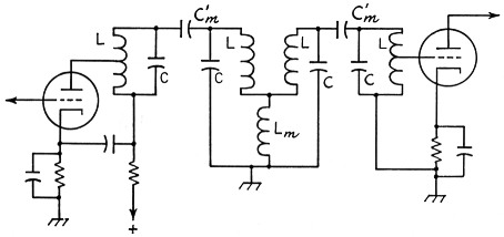
Fig. 3. Shunt- and series-coupling circuits can be combined for high-selectivity interstage coupling.
As will be seen later, the anode of the amplifier tube and the grid of the following amplifier stage are tapped down on the inductance L. This does not in any way alter the response of the coupled circuits, since for the case considered, L >> Lm and L >> Lt (Fig. 5). And because the coil is surrounded by a material of very high permeability, the coupling between the two parts of the coil is almost perfect and the circuit approximates an ideal autotransformer, transforming impedance and voltage.
Practical circuits
The complete circuit of a practical amplifier is shown in Fig. 4. The 455 kc. signal is heterodyned in the 6BE6 mixer to 20 kc. by beating with a 435 kc. crystal (obtainable from surplus stock) and amplified by a three-stage double-tuned selective amplifier designed to produce a maximum-flat-topped response. The 20-kc. signal is heterodyned to 1 kc. (or whatever audio note is desired by the operator) by beating with a stable series-tuned Clapp-type oscillator. The series-tuned trap in the output filter following the second mixer is tuned to 20.5 kc. to reduce the i.f. and b.f.o.-oscillator signals at the grid of the first audio amplifier. The b.f.o. is tuned to the high side of the signal frequency. An octal socket is wired so that a Selectoject can be used with the amplifier. When the Selectoject is not in use, an octal plug must be used to jump Pins 6 and 8. Other types of audio filters could also be used. (A double-tuned critically-coupled selective amplifier tuned to 1 kc., with a bandwidth of 30 cycles, has been experimentally used by the author with very excellent results.) The decoupling between stages may look elaborate, but adequate bypassing is quite difficult at 20 kc., where a 0.1 -µf. condenser looks like 80 ohms. After some experimentation the decoupling shown was adopted as a means of completely isolating the stages so the response curves are as calculated and not as modified by the regeneration introduced by the wiring.
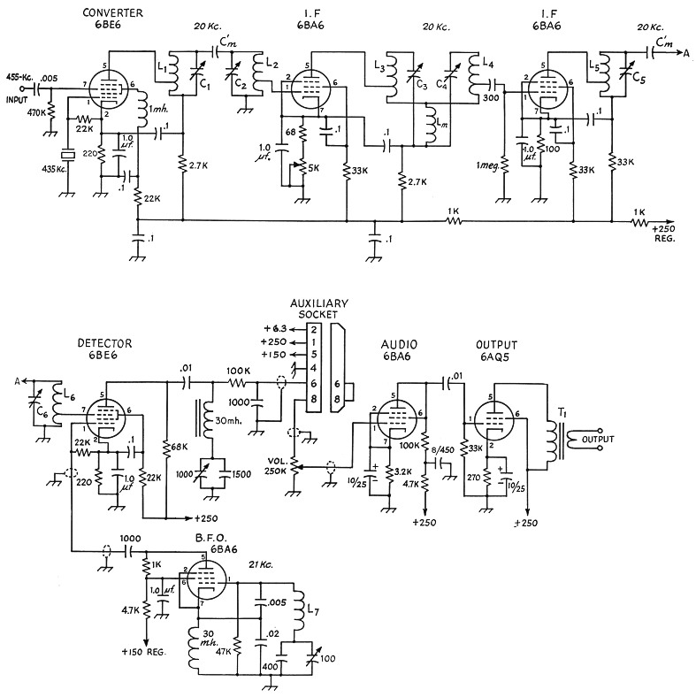
Fig. 4. Wiring diagram of the selective i.f. amplifier.
| C1-C6 | See text. |
| Cm | See text. |
| L1-L6 | See text. |
| Lm | See text. |
| L7 | 143 mH, Q of 20 to 30. |
| T1 | 5000 ohms to line output transformer. |
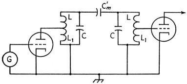
Fig. 5 - Equivalent circuit of an amplifier stage.
Design of the 20 kc. tuned circuits
The gain of an amplifier at resonance is
G = gm × Z
where:
gm = transconductance of the valve in mhos
Z = load impedance in ohms.
For double-tuned critically-coupled circuits,
Z = π × f × L × Q.
Now, if the anode of the amplifier and the grid of the following stage are tapped down on the filter, as shown in Fig. 5, the gain is
where:
L1 = inductance of tapped portion,
L = total inductance of coil.
This is so because the coefficient of coupling between L1 and L is almost unity when the windings are enclosed by a pot core.
Choose C = 0.0035 µF (convenient because a 0.003 µF fixed can be used with a 1000 pF trimmer);
then L = 18.1 mH.
For a stage gain of 60 with a coil Q of 180 and a 6BA6 tube (gm = 4400 µmhos),
L1 = 1.2 mH.
For the Ferroxcube type 25 pot core IIIB2 material with a 0.5 mm air gap (Philips type number D-25/17,5-11,00 - IIIB2)(6)
n = 65√L
where:
L = inductance in mH.
Hence, we need a coil of 284 turns of No. 34 enamel wire tapped at 71 turns. The coefficient of coupling
![]()
Hence C'm = 0.0055 (3500) = 19.4 pF (use 18 pF) and Lm = 0.0055 (18.1) = 0.1 mH. The coil Lm is wound on a small form having an adjustable slug. Each transformer assembly is completely enclosed in a sheet-metal box (20-gauge tinned steel) and short wires are brought out to connect to the external circuits. The boxes used by the author are 2 by 3 inches and 2 inches high. These are easily bent into shape and the corners of the box soft-soldered. Short bolts with the heads removed are soldered in the corners of the shield box to bolt the assembly to the chassis. The trimmer capacitors are Arco Electric type 307-M padders. These are good for this application because both plates are insulated from the mounting screw and the trimmer can be mounted directly onto the top of the shield box. The trimmer is mounted on the inside face of the top of the shield box, with the slotted bolt for adjustment projecting through the top of the can for ease of tuning. The pot-core assemblies are bolted directly to the side of the shield box.
The over-all bandwidth of the amplifier can be calculated from

n = number of identical stages. For the bandwidth at 3 db. (n = 3), m = 0.707, Δ f = 112 cycles. The response curve of the complete amplifier is given in Fig. 6. The bandwidth is 220 cycles at 20 dB down and 1000 cycles at 100 dB down.
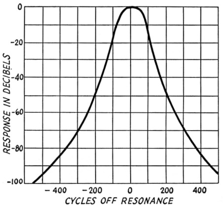
Fig. 6. Selectivity characteristic of the i.f. amplifier.
B.F.O.
In the unit constructed by the author, the b.f.o. inductor, L7, has a Q of about 25. The coil was wound in the form of 3 pies on a 1-inchdiameter bakelite rod. Commercially-available chokes could be used and turns removed to give the right inductance value. For Qs much different than specified, some adjustment of the feed-back condensers C2 and Cs and the anode load resistance will be necessary. The oscillator was built in a 3 × 4 × 5-inch metal utility box with the tube mounted on one side. The cathode choke coil was pi-wound on a small form. This choke coil is, however, readily obtainable from commercial stock. The oscillator tunes from 20.4 to 23 kc. The low-frequency limit is set by the fixed bandset condenser.
Power supply
Although an electronically-regulated power supply was used, it is not absolutely necessary. It does, however, provide a power source having a low output impedance at 20 kc., and thus lends to the over-all stability of the amplifier. The voltages are made available for use with external audio filters and clippers through an octal plug. It is convenient to be able to draw current from the power supply without upsetting the amplifier supply voltages.
Notes
- McLaughlin, "Selectable single sideband," QST, April, 1948.
- Githens, "Super-selective C.W. receiver," QST, August, 1948.
- Goodman, "All-purpose super-selective I.F. Amplifier," QST, May, 1953.
- Manufactured by Ferroacube Corporation of America, and Philips' Industries, Eindhoven. Obtainable in Canada through Rodgers Majestic; in Great Britain through Mul-lard Components Division, and in the U. S. A. through Ferroacube Corp., 97 Marshall St., North Adams, Mass.
- Sturley, Radio Receiver Design, Chapman Hall, 1953, p. 443.
- Pot cores D-25/17,5 have now been superseded by type D-25/16 (i.e., the total height of the assembly is 16 mm rather than 17.5 mm). The only important advantage of these new pot cores is that a greater air gap is available than with the older type. The maximum air gap in the former type was 0.5 mm., whereas in the new type 0.85 mm. air gap is available for the Grade 1IIB2 material. Grade IIIB1 is recommended for frequencies below 20 kc. whereas IIIB2 is recommended for frequencies above 20 kc. At 20 kc. similar Qs can be obtained with either type. For frequencies above 100 kc., use Type II1B3. It is recommended that, if this new line of cores is available, Type IIIB2 with an air gap of 0.85 mm. be used at 20 kc., since this will result in a slightly improved temperature stability (here N = 93»L).
These new cores have not been used by the author, but it is thought that Qs between 150-170 should be easily obtained, since a Q of 150 was obtained by the author using a Typo 25/17,5 pot core with an air gap of 1 mm. This air gap was experimentally ground by band. However, it is not recommended that the air gap be altered unless accurate micrometers are available to insure a uniformity of the cores. The material is very hard and brittle, and grinding even a few fractions of a millimeter off the slug is a long, tedious job.
J.S. Belrose, ex VE7QH, ex VE3BLW.