A broadband antenna for 75 meters
Impedance data on a fan-type dipole.
This article describes the results of measurements on one form of broadband dipole, constructed in the thought of reducing load variations throughout the 75-meter 'phone band. Other approaches are suggested for the amateur interested in experimenting with antennas for use on 80, 40 and 20.
Ordinarily, the mention of TV to the amateur inspires thoughts of interference and irate neighbors. However, the design of TV antennas has focussed attention on antenna measurements and antenna characteristics to a degree that merits the attention of amateurs interested in antenna design.
The writers have been interested for several years in the design of TV antennas. Both are active on 75-meter 'phone and both were interested in finding an antenna design which would perform in a uniform manner over the range from 3800 to 4000 kc. There also is considerable interest in c.w. operation, and therefore a design was sought which not only would perform well in the 'phone section of the band but would also work satisfactorily over the range of 3.5 to 4 Mc.
The most obvious solution to the problem of designing a good broadband antenna was the conical type using the minimum number of wires possible to produce the effect of a radiator of large conical section.
Some time ago, the Collins Radio Company suggested a simple conical- or fan-type dipole as a good broadband antenna for an amateur transmitter.(1) Other references to such an antenna are to be found in the literature, but nowhere were there any measurements to indicate what might be expected from a fan or conical design at 3.5 to 4 Mc. Modern literature is extensive on conical-type antennas in the v.h.f. and u.h.f. ranges.
To determine what might be expected of a conical design having reasonable dimensions, an antenna was constructed in which each half of the dipole consisted of two wires joined together at the center of the dipole and fanned about 8 feet at the extreme ends of the antenna. A beginning was made with an overall length of 120 feet and tests were made while the antenna was pruned until resonance at 3900 kc. was achieved with an over-all length of 107 feet. The Collins literature mentioned earlier had indicated a length of approximately 110 feet for the 75-meter 'phone band. During the pruning operation the standing-wave ratio of the 52-ohm RG-8/U transmission line was observed using a Millen r.f. bridge. After the resonance point had been reached, measurements were continued with a General Radio 916A r.f. bridge.
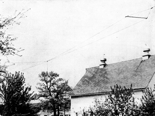
The "hiconical" or fan-type 75-meter antenna at Vl9SZ, on which the measurements discussed in this article were made.
The antenna height for all the measurements was about 35 feet, which is a common height for many 75-meter antennas.
The photographs illustrate the configuration of the antenna, and the wire saddle and weight employed to hold the wires in a horizontal plane. The spreader is an 8-foot length of light-weight aluminum tubing flattened and pierced at the ends for attachment of the antenna insulators. The two wires were individually insulated on each side of the dipole at their outer ends.
Tests were made with the fanned wires in both the horizontal and vertical planes, with no noticeable difference in operation or in the measurements for either plane.
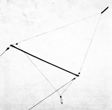
Saddle and weight arrangement used to hold the spreader in a horizontal position.
The characteristics of the antenna were found to be quite suitable for 75-meter phone operation and for c.w. operation between 3.8 and 3.5 Mc. It had been estimated that the antenna might be expected to perform reasonably well on the 20-meter band, also. Measurements were taken on the 75- and 80-meter bands, the 40-meter band and the 20-meter band. The results and actual operation confirmed the estimate that 20-meter operation might be obtained with this design.
Table 1 gives the values of impedance at the terminals of the antenna. The values of resistance and reactance are shown, along with the v.s.w.r. that would be exhibited by these values in reference to a 52-ohm coaxial transmission line such as RG-8/U. The table indicates that the antenna is very close to resonance at 3.9 Mc. as was found with the Millen s.w.r. bridge. However, throughout the 3.5- to 4.1-Mc. range the values of reactance are of such magnitude that they can be tuned out easily by any of the conventional methods. Measurements were carried up to 4.1 Mc. to determine the effect of an additional increase in frequency beyond 4.0 Mc.
| Frequency, Mc. | R, Ohms | X, Ohms | V.S.W.R. |
|---|---|---|---|
| 4.10* | 42.85 | +37.90 | 2.2 |
| 4.00 | 39.75 | +14.55 | 1.5 |
| 3.90 | 39.00 | -9.36 | 1.4 |
| 3.80 | 39.00 | -32.20 | 2.1 |
| 3.70 | 43.85 | -58.50 | 3.2 |
| 3.60 | 50.90 | -88.40 | 4.8 |
| 3.50 | 78.00 | -114.3 | 5.2 |
Fig. 1 gives a comparison of the characteristics of the fan-type dipole and a conventional full-length dipole with a single wire each side of center. The resistance and reactance characteristics of the fan-type dipole are plotted on the basis of the measurements made.(2) Data points for the conventional dipole were obtained by calculation from information in the ARRL Antenna Book. Resistance and reactance are shown for percentage departure above and below the resonant frequency. While the resistance values for each type of dipole remain fairly constant over the frequency range, there is a very noticeable difference in reactance variation. The fan-type dipole shows a more gradual reactance slope than the conventional dipole over the entire 75-80-meter band. Actual numerical comparison of the slopes shows that the reactance of the conventional dipole changes twice as fast as the reactance of the fan-type dipole.
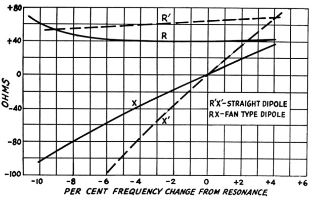
Fig. 1. Impedance characteristics of fan-type dipole as compared with a conventional wire dipole. Fan-dipole values are measured; conventional-dipole values are theoretical.
Other bands
Table 2 gives the values of resistance and reactance of the antenna in the 40-meter band. Although the reactance appears to be large, the antenna can be successfully tuned for operation within this band. However, it must be pointed out that if connected to a 52-ohm coaxial line, the resistive values of the antenna indicate that this type of operation would represent a poorer compromise than is usually acceptable.
| Frequency, Mc. | R, Ohms | X, Ohms |
|---|---|---|
| 7.0 | 177 | +260 |
| 7.1 | 140 | +234 |
| 7.2 | 104 | +218 |
| 7,3 | 114 | +208 |
Table 3 gives the measured values of resistance and reactance on the 20-meter band. In this case it is found that the reactance is small and the values of resistance are much closer to the 52-ohm impedance of the transmission line. Therefore, operation of the antenna in this band would be much more practical than on 40 meters. Thus, it is apparent that the antenna operates well on the 75- and 20-meter bands, whereas on 40 the performance would not be acceptable.
| Frequency, Mc. | R, Ohms | X, Ohms |
|---|---|---|
| 14.00 | 22.8 | -45.7 |
| 14.10 | 34.8 | -62.4 |
| 14.20 | 29.6 | -48.3 |
| 14.30 | 29.6 | -52.0 |
| 14.35 | 31.2 | -55.6 |
| 14.40 | 31.2 | -56.7 |
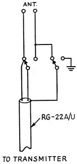
Fig. 3. Suggested switching arrangement for changing the characteristic impedance of the shielded transmission line to give a better match on different bands. Switches are thrown to the right for 7 Mc.; to the left for 4 and 14 Mc.
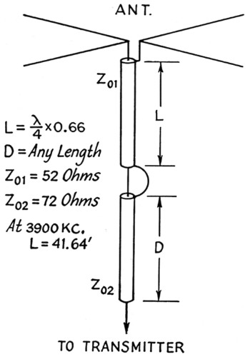
Fig. 2. Quarter-wave transformer for matching the fan dipole to 72-ohm coaxial line.
Matching possibilities
The tables indicate that a better match for 75-meter operation might be obtained with a quarter-wavelength transformer. A quarter-wave section of RG-8/U coaxial cable inserted between the antenna terminals and an RG-11/U 72 ohm coaxial cable would match approximately 37 ohms at the antenna. It is obvious that such a transmission line and matching transformer would provide optimum matching conditions for operation between 3800 and 4000 kc. It will be noted that below 3800 kc. the resistance of the antenna rises and more nearly matches a 50-ohm transmission line than the combination of a 72 ohm coaxial cable together with the quarter-wave matching section of 52-ohm cable. Fig. 2 shows the 72-ohm coaxial feed system with the 52-ohm matching section dimensioned for operation at 3900 kc. Another suggestion which would provide a close match at 75 and 20 meters, and at 40 meters as well, is indicated in Fig. 3, in which RG-22/U or RG-22A/U coaxial cable can be used with a simple d.p.d.t. relay to provide 95 ohms impedance for 40-meter operation and approximately 47 ohms transmission line impedance for operation at 75 and 20 meters.
General
In all of the measurements, the antenna was fed with a single RG-8/U coaxial line of 52-ohm characteristic impedance. The data, however, are referred to the antenna terminals. It is well to point out that in order to reduce unbalanced currents on the surface of the shield braid, the feed line must be brought away from the antenna at a right angle.
The antenna was installed and tested at W9SZ near Lemont, Ill., and was operated over a period of several months. During that time it was found that numerous other amateurs were using similar antennas for broadband operation on the 75-meter band. W9AOV and several other members of the Illinois Emergency Net were found to be using antennas based on the Collins suggestions. Another was W9DKU, and W8PUN reported that he had been using such an antenna since 1937. All of the amateurs contacted were very much interested in the measurements which were being made, and reported that excellent results had been obtained. With this general type antenna the end spreading varied among the users from 8 feet to 12 feet.
Incidentally, the shortening which is achieved by the spreading of the ends of the fan-type dipole may be helpful to the amateur who must install his antenna in a restricted space, whether he is interested in broadbanding or not. It could be expected that the length reduction of approximately 10 per cent which applies at 75 meters would apply also at 40, 20 and 10 meters and permit the antenna to be installed between two appropriately spaced trees or within the amateur's lot lines.
Notes
- "Antennas with 52 Ohm coaxial feed lines," published by Collins Radio Company, Cedar Rapids, Iowa.
- The rise in the resistance component of the fan dipole impedance in the lower part of the frequency range is contrary to the theoretical behavior of radiation resistance as the antenna is progressively shortened. It is possibly the result of the presence of other conductors in the vicinity, or may be associated with the antenna height, which was 0.15 wavelength in these tests.
Charles C. Camillo, W9GZJ
Richard M. Purinton, W1SX.