A 200 watt grounded-grid linear amplifier
Unusual design using four modified 1625 tetrodes.
Here is the design for a compact self-contained linear amplifier that shows considerable ingenuity. Some of the old hands in ham radio will be taken back to the "good old days," when it was the custom to operate on the available vacuum tubes by debasing them or sawing slots in the base. In this case, the authors show how to get a new tube type from a conventional design.
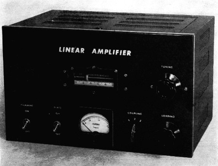
This clever linear amplifier uses four parallel-connected tetrodes in a grounded-grid circuit. It can be driven by an s.s.b. exciter capable of 20 watts peak envelope power output. The cabinet is only 14A by 9 by 10 inches deep.
Grouded-grid amplification in linear service has several advantages over conventional circuits. The amplifier is degenerative, which adds to its stability. It has been found that it produces slightly better linearity than conventional circuits using the same tubes.(1) And, of course, the greater part of the power required to drive the grounded-grid amplifier appears in the output along with the amplified signal. The disadvantage of using the 807 or 1625 in this type of operation is that the beam-forming plates are connected to the cathode. The signal appears on the cathode, and the beam-forming plates form good coupling capacitors to the plate. This couples the input and output circuits and causes instability. We thought that we would be able to stabilize an amplifier with these tubes if there were only some way to ground the beam-forming plates directly, since this would help to isolate the input and output circuits. Checking various makes of 1625s showed that, in many instances, the beam-forming plate lead was attached to the cathode lead in the cathode pin. Bases were removed by applying heat from a large torch. The cathode and beam-plate leads were then separated and new 6-pin bases reinstalled, using the same cement that the manufacturer uses. They were then baked in an oven at 90 degrees C. to harden the seal.(2)
The modified tubes were found to do an excellent job, and further simplification of design was now possible. Using four of the tubes in parallel brought the cathode impedance down to about 50 ohms, so it offers a good load for most popular exciters.
Since the input circuit of the grounded-grid amplifier is a low-impedance load for the driver, it is possible to do away with any input tuned circuit; the d.c. return for the 1625s is made through the exciter output tap or link. A word of caution here - be sure there is no d.c. on the exciter link, because the 1000-ohm safety resistor would short it to chassis.
We found that no bias or screen voltage was required at 1200 volts on the plate. Each tube draws about 10 mA, so the power supply is constantly bled with 40 mA, thus eliminating the need for a bleeder.
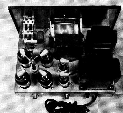
A top view of the linear amplifier shows the r.f. tubes at the left, clustered around the r.f. choke. The tyro small tubes are the 816 rectifiers used in the 1200-volt power supply. The variable inductor will be recognized as the antenna loading coil from a BC-458 Command transmitter.
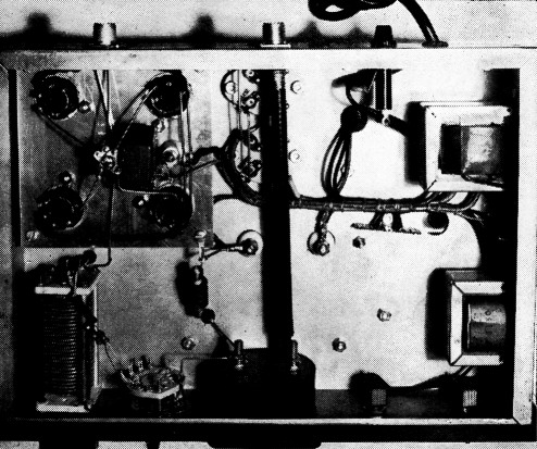
This bottom view shows how the four r.f. tube sockets are mounted on a small platform. The 2.5 mH choke across the output circuit is to prevent accidental shock from the antenna system in the event that the plate-blocking capacitor should short circuit. Filament transformers are mounted on the side of the chassis.
Now, with no screen and bias supply and no input tuned circuit, it was possible to design and build a compact amplifier. We chose the pi-network output circuit with variable inductor to cover 75, 40 and 20 meters. We felt that 15-and 10-meter operation was impractical because of the high output capacitance of the four tubes used in parallel. The circuit diagram is shown in Fig. 1.
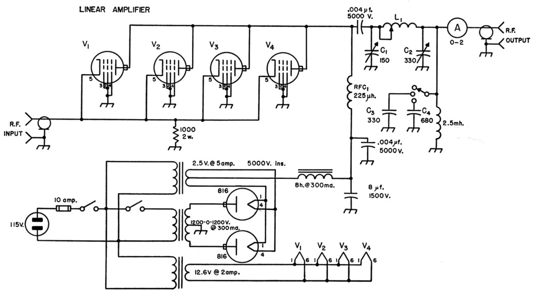
Fig. 1 Schematic diagram of the grounded-grid amplifier. Capacitor values in µF unless otherwise specified.
| C3,C4 | 600 volt silvered mica capacitor. |
| L1 | 2.0 µH roller-type variable inductor (from BC-458). |
| RFC1 | National R-175A. |
| V1,V2,V3,V4 | Modified 1625 - see text. |
Construction
The unit is constructed on a 10 × 14 × 3 inch chassis, and a 5¼ × 5¼ inch subchassis on which are mounted the plate r.f. choke and four 6-pin tube sockets. This subchassis is mounted 14 inches below the main chassis deck. The cold end of the r.f. choke is by-passed through a 0.004 µF capacitor to a soldering lug at the center of the subassembly. The lug is mounted beneath a 1-inch stand-off insulator, and a single stud screw holds the choke and stand-off to the subchassis. A feed-through insulator on the subchassis feeds d.c. to the choke and also serves as a tie point for the "hot side" of the by-pass capacitor. The screen grid, grid, and beam plate are grounded to the subchassis as close as possible to each tube socket. The cathodes are connected at the central standoff insulator, which is also the tie point for the r.f. input lead.
The cabinet is 10 × 14½ × 8¾ inches with a panel to fit. The rotor indicator of the inductor and input capacitor are mounted on the panel and the panel secured by the output rotor switch, meter and toggle switches. The 0.004-0. d.c. blocking capacitor mounts on the rear of the input-tuning capacitor, C1.
An r.f. choke was included across the output of the pi-network, so that in the event of a shorted d.c. plate blocking capacitor the power supply fuse would blow. This keeps 1200 volts d.c. off the antenna system.
If plate voltage were applied with no input connection for the cathode return, full plate voltage would appear between cathode and filament. A 1000ohm resistor is connected from cathode to ground to prevent this from occurring.
Operation
The tune-up procedure is the same as for any pi-network amplifier. The whole coil is used for 75 meters, about half for 40 meters, and one-fourth for 20 meters. Initial tuning adjustments are made with about half the available r.f. drive power. Twenty watts of drive will put a good signal on the air.
The input and output circuits in this design are well shielded by the grounded grid, screen, and beam-forming plates, and no trouble with fundamental or v.h.f. instability has been experienced. Although this amplifier is designed primarily for s.s.b., it may also be used to amplify a low-powered a.m. or c.w. signal.
Notes
- Puckett, "Notes on grounded-grid r.f. power amplifiers," QST, Dec., 1954.
- The modified tubes can be obtained from P & H Electronics, 5 N. Earl Ave., Lafayette, Ind. Cement for doing the job yourself can be obtained from the same source.
E.L. Hoover, W9SAR
R.L. Peck, W9MOW.