Guys for guys who have to guy
Calculating load of rotary beam supports.
This article tells how to calculate the wind load on a mast or tower supporting a beam antenna, and the amount of guying required to make the installation safe. In his spare time from ham radio, W6FHR is a structural engineer for one of the major aircraft companies.
Each year, as the competition for available amateur space has become keener and keener, antennas have grown steadily higher and higher. Time was when a wire a few feet above ground would cut a healthy swath across the bands. The average ham was usually satisfied with a wire between a 2 X4 on the roof and the old oak tree in the yard. If the thing came down, you were off the air for only a few days, and nothing more. Then some enterprising fellow found he could do better if he raised his wire, and the race for height was on. Today, some installations rival the Tower of Babel.
For sticks of 20 or 30 feet, almost any sort of guying usually will be sufficient. But as we start reaching for heights of 50 feet and upward, with beam arrays, the problem becomes magnified, involving the element of danger to life and property. After listening on the air to some descriptions, one can only take comfort in the old adage, "The Lord protects fools and drunks," which, it appears, should also include hams.
Beam load
In designing a system of guys, the total wind load on the antenna and tower for some safe value of wind pressure must be determined. Contrary to general opinion, the weight placed on the top of the tower is relatively unimportant compared to the wind load. The top load will usually take care of itself when the wind load is compensated. In fact, the vertical components of the tension load of the guys themselves will, in all probability, exceed the top weight of the average amateur installation.
In calculating the wind load for which the guy system should be designed, the requirements of the local building codes should be observed. While the figure will vary from community to community, a general allowance of a unit wind load of 30 lbs. per square foot of exposed area will meet most regulations. For round cross sections, such as beam elements or round poles, two thirds of this value, or 20 lbs. per square foot is permissible.(1) In hurricane belts or localities where abnormal winds or icing can be expected, your local building department should be consulted for recommendations.
The total wind load will be
![]()
where P is the unit load in pounds per square foot, and A is the total projected area in square feet.(1) The projected area of members of round cross section section is the length times the diameter; for rectangular cross sections, it is the length times the diagonal of the cross section.(2)
Let us take a typical 20-meter beam, such as sketched in Fig. 1, as an example. The projected area of the elements is calculated first. Since the elements are made up of sections of different dimensions, the areas of each section must be calculated separately, and then added. The area of the three 12-foot center sections is
![]()
The projected area/ of the outer sections of the elements is
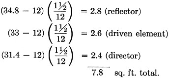
The total projected area of the elements is
![]()
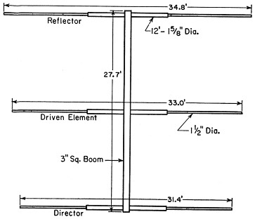
Fig. 1. Typical 20-meter parasitic beam whose dimensions are used in a sample calculation.
Using a unit wind load of 20 lbs. per sq. ft. (because the elements are round), the wind load on the elements is
(20)(12.8) = 256 lbs.
The boom in this example is square, so we must use the diagonal of the cross section in computing the area, and a pressure of 30 lbs. per sq. ft. in calculating the load. The diagonal of a 3-inch square is 4.25 inches, so the projected area is
![]()
and the boom load is
![]()
Thus the critical load is on the boom, and it is this load that is used for the load L in Figs. 2 and 3.(3)
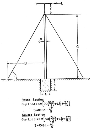
Fig. 2. Diagram and formulas for a system using a single set of guys. *See text for calculating d for lattice masts. All dimensions should be in feet. Dimension T should be held to a minimum.
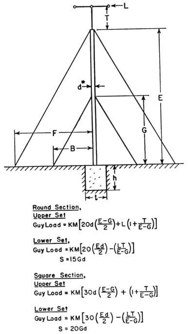
Fig. 3. Diagram and formulas for a system using a double set of guys. *See text for calculating d for lattice masts. All dimensions should be in feet.
Tower load
Having obtained the antenna wind load, the load of the tower should now be calculated. The dimension d in Figs. 2 and 3 is the diameter of a pole of round cross section, or the diagonal of a mast of square cross section.
If the tower is of latticed construction, the resulting load will be conservative if the surfaces are considered to be solid. Alternatively, if the actual area is used, it should be increased by 50 per cent. If the latter is used, an effective d must be determined. This is the diagonal cross section of a solid mast having the same total surface area. If, for example, the construction is that shown in Fig. 4, the total area for each bay is
![]()
The actual area is the total area minus areas A, B and C. B = A + C, so the area to be subtracted is 2B. The area of B is
![]()
120 - 60 = 60 sq. in. actual area per bay. Increasing this by 50 per cent, as mentioned above, gives a figure of 90 sq. in.
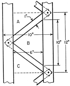
Fig. 4. Typical section of lattice mast discussed in the text.
A solid section 12 inches long, hsjving an area of 90 sq. in., would have a width of
![]()
Multiplying by 1.4 to obtain the diagonal gives
![]()
This is the d that should be used in Figs. 2 and 3. Tables I and II give the values of K and M.
| Angle A | B/G or F/E | K |
|---|---|---|
| 59° | 0.6 | 1.94 |
| 51° | 0.8 | 1.60 |
| 45° | 1.0 | 1.41 |
| 40° | 1.2 | 1.30 |
| 36° | 1.4 | 1.23 |
| Guys in Set | M |
|---|---|
| 3 | 1.150 |
| 4 | 1.000 |
| 5 | .649 |
| 6 | .578 |
| 7 | .457 |
| 8 | .415 |
Guy wires
Guy wires are usually set at an angle of 45 to 60 degrees with the horizontal, and unless absolutely necessary, this angle should never exceed 60 degrees. Table III gives the breaking strength of 6 × 7 galvanized sash cord which makes excellent guy wire. Other types of cable will work equally well. However, regardless of the type selected, the guy should have a breaking strength of 4 times the calculated load. The loads calculated by means of Figs. 2 and 3 are, of course, the load on each guy.
| Diam. (in.) | Breaking Strength (lbs.) |
|---|---|
| 1/16 | 126 |
| 3/32 | 283 |
| 1/8 | 504 |
| 5/32 | 756 |
| 3/16 | 1035 |
| 7/12 | 1413 |
| 1/4 | 1836 |
Base
The cross section of the base supporting the tower may be calculated by the use of the following, referring to Figs. 2 and 3.
![]()
where t is the side of a square base in feet, and W is the combined weight of the tower, beam and base in pounds. (Concrete weighs about 144 lbs. per cubic foot.)
The depth of the base is determined by
![]()
where h is in feet and t and S are given in Figs. 2 and 3.
One last word of caution: Guys should have only sufficient tension to take up any obvious slack.
If the design principles outlined here are followed, your tower should withstand any of the elements with a minimum of maintenance.
Notes
- Wind load on a flat surface is about 50 per cent greater than on an equivalent surface of a member of round cross section.
- Although the wind load on a member of square cross section with a corner pointing into the wind is less than on an equivalent flat surface, this fact is neglected in most building codes, and the projected area is treated as though it were flat.
- Under certain circumstances, the total wind load on elements and boom, with winds at angles other than a right angle might be somewhat greater than either of the two calculated loads. However, this design is sufficiently conservative to permit the simplification.
Lewis H. Abraham, W6FHR.