Lightning protection for the transmitting antenna
Grounded system for open-wire feeders.
Lightning protection for the amateur transmitting antenna, especialy when open-wire feeders are used, has been largely neglected. W4ZG points out the dangers involved and offers some simple solutions.
An old adage says lightning never strikes twice in the same place. You may not agree with this, but if it strikes you once it won't make any difference whether you do or don't agree.
Radio amateurs for the most part invite destruction by lightning by neglecting to provide any protection against it. The antenna usually associated with amateur radio transmitting equipment is most vulnerable to lightning due to its length and height. To validate your insurance, your antenna installation must comply with the National Board of Fire Underwriters Electrical Code which says:
Lightning Arresters - Transmitting Stations. Except where protected by a continuous metallic shield (coax) which is permanently and effectively grounded, or the antenna is permanently and effectively grounded, each conductor of a lead-in for outdoor antenna shall be provided with a lightning arrester or other suitable means which will drain static charges from the antenna system.
A similar requirement is applicable to a receiving antenna should it extend outside the building in which the receiving equipment is located.
Many years ago my antenna was struck by lightning. At that time, there was an insurance requirement which said that a 100 ampere switch should be used for grounding the antenna when the station was not in operation. The lightning completely destroyed most of the antenna wire, burned the wooden base of the lightning switch and burned the insulation off the No. 4 copper grounding wire between the switch and the ground stake. As the switch was in the grounded position, no damage to the house or radio equipment resulted.
Without adequate grounding, hazardous voltages can build up on an antenna due to other causes. About 1920, while attending Carnegie Tech, Pittsburgh, Penna., an experience was observed which will be of interest in this connection. The antenna at 8XC consisted of 10 wires 600 feet long, approximately 165 feet above the ground at its center. It ran across a gully, at the bottom of which was a mainline railroad track. When locomotives pulling heavy trains passed under the antenna, the static charge built up was sufficient to cause flash-over of an 8 inch gap. The flash repeated approximately every five seconds while the engine was immediately beneath the antenna and less frequently when it was approaching or leaving the area below the antenna.
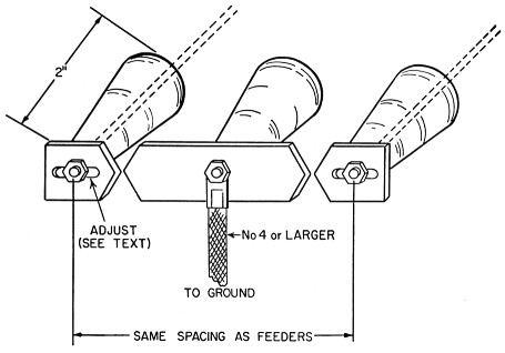
Fig. 1. A simple lightning arrester made from three stand-off or feed-through insulators and sections of u-inch-thick brass or copper bar.
Lightning arresters
What steps should we take to protect ourselves and our equipment against these hazards? You will observe that the Electrical Code specifies that the lead-in may be a coaxial cable, the shield of which is permanently and effectively grounded. This means that a ground connection, using No. 4 wire or larger, should be made to the shield of the coaxial cable at the point where it is nearest to the ground outside of the house. If the cable can be run underground, a grounding stake should be located at the point where the cable enters the ground. The grounding stake, to be effective in soils of average conductivity, should be not less than 10 feet long, and if possible, plated with a metal which will not corrode in the local soil.
When open-wire feeders are used, a lightning arrester is required. The type of lightning arresters provided for residential broadcast and television antennas may be suitable for very low-power installations but where higher power is used, they are inadequate, since the radio-frequency voltage on the transmission line is usually enough to cause them to operate; i.e., flash over.
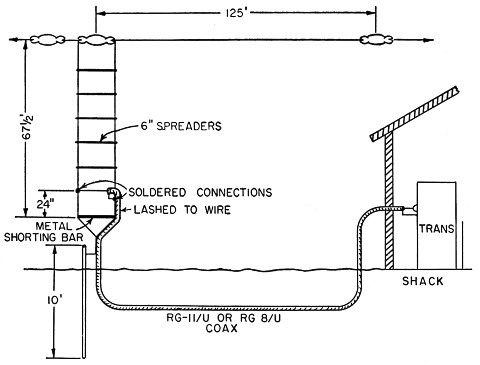
Fig. 2. Sketch of coax-fed grounded Zepp antenna. Adjustment is discussed in the text.
During the early Thirties, advice was obtained from the Naval Research Laboratory at Washington, D.C., on a suitable grounding arrangement for lightning protection for a 1 kW installation. It as their suggestion that a spark gap be provided between each of the two open-wire feeders and a center contact, grounded with No. 4 or larger wire. It was recommended that 1/8 × ½ inch flat brass rod shaped as shown in Fig. 1 be used or the gaps. Each of the gaps should be set sufficiently far apart so as to prevent flash-over during normal operation of the transmitter. It as found that because of the standing waves on the open-wire line a gap of approximately 3/16 inch was necessary.
This device worked very well during thunderstorms as it would start sparking intermittently when a storm was approaching. As the storms passed over the immediate area, the frequency of discharge would increase. During heavy thunderstorms, there was a steady stream of parks at the gaps. It was possible to operate the transmitter with relatively little effect on its performance even while the static charges were jumping across the equipment, but this was seldom done because of a personal reluctance be so close to the antenna system. It has been my belief that a properly installed spark gap on an antenna system drains off sufficient static from the immediate area to prevent a direct hit. This view stems from that fact that during the twelve years these gaps were in use there was never an occasion when a lightning hit came closer to our house than a half block when a neighbor's house was struck. This could have been a happenstance but it is the fact, nevertheless. In the Pennsylvania Dutch country around Lancaster and York, most barns nowadays are protected from lightning by a length of old trolley wire mounted on poles extending about 10 feet above the roof. Both ends of the wire are grounded and, so far as can be learned, no barn so protected has suffered lightning damage.
Direct ground connection
Many of our modem antennas permit relatively simple methods of direct ground connection, which do not interfere with the operation of the antenna. Rotary beams using a T or gamma match may have the center of each of the elements, including directors and reflectors, grounded to the tower on which they are mounted. Two-and six-meter beams should have the supporting pole grounded. If the antenna is mounted on a wooden pole or on the top of a house, a No. 4 or larger wire should be extended from the beam to the ground, using insulators where the wire comes close to the building. The ground wire should be spaced away from metal objects such as gutters, etc., or should be solidly grounded to them. If the connection to such objects is not a good one, but is variable in resistance, it may be a source of spurious signals when excited by the transmitter. This often results in interference with your own or your neighbors' broadcast or television reception.
For the past seven years, the antenna shown in Fig. 2 has been used at W4ZG, Winston-Salem, N.C. It gives what appears to be good lightning protection. It hasn't been hit yet. And best of all, signal reports have been more than satisfactory on power comparisons made with other stations under like conditions.
The antenna may properly be called an end-fed Zepp. Since much of the work done here is on the Tar Heel Net frequency of 3865 kc., the antenna was cut to center on this frequency. Operation is not confined to this frequency, however, as many contacts are made even at the high end of the band without any retuning or adjustment of either the driver or final-stage tuning circuits.
The antenna is 125 feet long and the quarter-wave Zepp feeders are 62½ feet long, spaced 6 inches apart. The feeders are tied together at the lower end and grounded. A metal rod 6 inches long is used as the lowest spacer. RG-11/U (72-ohm) coax is used to feed the Zepp feeders. The shield of the coax is attached to the feeder which goes to the antenna and the center conductor goes to the other feeder which dead ends at the antenna. The point of attachment is about 24 inches from the shorting bar. The coax is tied to the feeder to which the shield is connected and follows it back to the shorting bar and then follows the ground lead to the ground stake and from there runs underground to the house.
By now you are wondering why the shield is connected to the feeder which goes to the antenna instead of being attached to the feeder which dead ends. Actually, it makes no difference which way you do it, except that if you use a bridge to check the standing-wave ratio, you will have more trouble with induced voltages from local broadcast stations if you reverse the connection, since the feeder plus antenna picks up much more of this broadcast field voltage than the dead-ended feeder alone will pick up.
Another benefit from this antenna which was entirely unexpected is the reduction in harmonics reaching the antenna. At the desired frequency, the 4 feet of wire between the ends of the coax and the shorting bar serve as a transformer to match the impedance of the coax to the impedance of the open-wire feeders. At other frequencies, however, this is not the case, and the higher-order harmonics are effectively suppressed. No other filter is used at W4ZG for this purpose and there is no observable interference on a television receiver connected to an antenna just 15 feet away from the Zepp feeders.
Should you wish to use this antenna on other bands, you may do so by reducing the dimensions in accordance with standard antenna formulas. The point of connection of the coax to the Zepp feeders is not critical and may vary somewhat under different surrounding conditions. It can best be done by measuring the s.w.r. at the transmitter end of the coax at several different test positions, but if no bridge is available, the connection of the coax to the Zepp feeders may be made 24 inches from the shorting bar for 80 meters, 12 inches for 40 meters, 6 inches for 20 meters, and 3 inches for 10 meters.(1) It is desirable that the feeder spacing be reduced at the higher frequencies as the length of the shorting bar is a factor in the impedance match.
Notes
- For antenna systems in which the antenna and feeder lengths are the same as above in terms of wavelength. - En.
R.C. Corderman, W4ZG.