Low-noise receiver design
Technical Editor, QST:
In the March issue the article on "Low-Noise Receiver Design" by Longerich and Smith was to me both interesting and profitable, since it enabled me to bring my receiver up to an acceptable level. I have an old HQ-120-X which I bought a couple of years back for $65. My first attempt at improving the performance involved changing the grid-cap tubes for more modern single-ended types of higher gm. This resulted in considerable improvement on the lower bands, but in substantially no improvement on the bands above 7 Mc. Believing at the time that the trouble lay in poor image rejection (with an i.f. of 455 kc. and only one r.f. amplifier this is a possibility) and in oscillator pulling, I was in the process of changing over to dual conversion on the three high bands of the receiver (above 5.7 Mc.) with a first i.f. of 5.0 Mc. However, before I had gone very far with this I noticed the above article, and it has done the trick. The cathode follower on the oscillator has eliminated the pulling (if there was actually an appreciable amount present), and the increase in r.f. tank circuit Q occasioned by the use of the cathode followers has improved the image ratio. This increase in Q, incidentally, has made the tracking more critical, but not enough so to be a serious problem. But, of course, the major improvement has been in the terrific reduction in receiver self-noise. I now feel that I have a receiver which is equal or superior to anything in the $300 class.
There were, however, several items in the article which I feel were mistakes, and others which were open to considerable question. One of the items you pointed out, which was that two r.f. amplifiers are not necessarily better than one, since the primary function of the r.f. stage (noise-wise) is to override the noise of the mixer. (Of course, for image-rejection purposes, the more r.f. stages the better, but the law of diminishing returns sets in very rapidly.) In the present instance one r.f. stage is more than ample from the noise consideration, since the equivalent noise resistance of a 6AC7 triode mixer is
Req = 4 / gc = 44 / (gm / 4) = 16 = gm = 16 / .011
which is about 1450 ohms! (The equations used may be found on page 937 of Radiotron Designer's Handbook, 4th ed.) Therefore, the limiting resistance for noise production is the r.f. stage, which has an Req = 2.5 / gm = 230 ohms.
Let me back up a bit and substantiate that "therefore" in the last sentence. Assuming a minimum gain of ten times from the grid of the r.f. stage to the grid of the mixer, the effective resistance of the mixer at the grid of the r.f. stage would be 1450/10 or 145 ohms. The gain of the r.f. stage in the original receiver was 10, and if anything, it is greater in the present configuration. This is based on the consideration that the is of a triode-connected 6AC7 is 40, and the Q of the tank circuit has been increased. Hence, the mixer resistance translated to the r.f. grid would be less than 145 ohms, and the 230 ohms of r.f. tube equivalent resistance at the grid of the r.f. amplifier would be the controlling factor in noise production.
Another error, which is in some ways more obvious, is the application of a.v.c. voltage to the grid of the 2nd r.f. amplifier cathode follower in Fig. 1 of the article. If A is the gain of the tube in a normal grounded-cathode amplifier application, then the gain of a cathode follower is
A' = A / (1 + A)and since the gain of a 6C4 is about 10 or 12, this fraction would be in the neighborhood of 12/13 or about 0.92. If the gain of the tube were reduced to ½ by a.v.c. action, or to a gain of 4, then the cathode-follower gain would be reduced to 4/5 or 0.8. This is not my idea of very good a.v.c. action, since it would result in a reduction of gain of small percentage for a large value of a.v.c. voltage. A more practical method would be to apply the a.v.c. (or even better, partial a.v.c.) to both r.f. and mixer grounded grids, grounding the grids for r.f. through a 0.01 µF capacitor. In my receiver, applying no a.v.c. to the r.f. stage or mixer resulted in severe cross-modulation in the presence of strong adjacent signals, particularly on the broadcast bands. This was eliminated completely upon application of ½ a.v.c. voltage to the r.f. and mixer grids as indicated above.
In addition, the authors quoted a transconductance of 11,000 for the triode-connected 6AC7. However, the tube manual gives this value of gm only for a plate voltage of 150 volts and a cathode bias resistor of 160 ohms. Under these conditions the plate current is 12.5 mA, and this results in a bias of -2.0 volt. The 1500 ohm cathode resistor used by the authors in Fig. 1 is certain to result in a smaller effective value of gm for the operating conditions, producing a smaller gain, and more important, more noise. I used a cathode resistor of 700 ohms in both 6AC7 stages, and would bave used a smaller value if the gain had appeared to be insufficient. There should be no difficulty in obtaining sufficient driving voltage even with a cathode resistor of only 100 to 200 ohms, because of the low-impedance output of the cathode follower. I have not been able to obtain a set of characteristics for the triode-connected 6AC7, so I have no idea how the variation of plate voltage will affect the picture, but as a general thing, the greater the bias voltage applied, the less the transconductance.
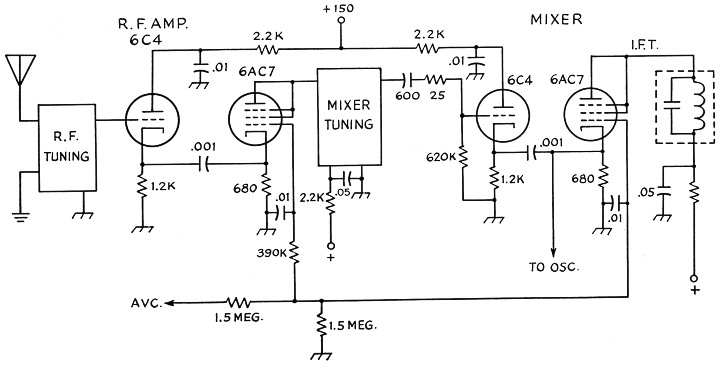
Fig. 1. Revised front-end wiring of an HQ-120. The oscillator schematic is shown later.
Another small point: In Fig. 1 of the article, it is not necessary to provide the 47 pF coupling capacitor and the 47K resistor to the grid of the cathode follower on the oscillator stage. The d.c. level at the cathode of the oscillator is not sufficient to affect the operation of the cathode follower, being only a few millivolts; compared to that at the cathode of the cathode follower it is negligible. Furthermore, either the Hartley or the tickler-feed-back oscillators shown in Fig. 2 can be used as a grounded-plate oscillator. The Hartley circuit is so shown in Fig. 2; the tickler circuit need only be changed to look as follows:
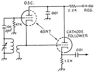
Fig. 2.
This results in a somewhat simpler arrangement than that shown in Fig. 2, and uses about three components less. This ie the oscillator circuit as I used it in my receiver. It is to be noted that the polarity of the feed-back coil must be observed - the end previously tied to the plate must go to ground to maintain oscillations. In my opinion this configuration results in a more nearly constant output as frequency is varied, due to the slight degeneration inherent in having a r.f. potential at the cathode. In addition, the signal is not taken from the tank circuit of the oscillator, which improves the isolation somewhat.
In closing, let me say that in my case the article was very timely and much appreciated. I am enclosing a sketch of the complete front end on my HQ-120 as it now is wired.
Robert Irving, Lieut., USN
Technical Editor, QST:
Before proceeding with individual points it might be well to examine the equation for the noise figure of the input stage of a system as given by Goldberg ("Some notes on noise figures," I.R.E. Proceedings, October, 1948).
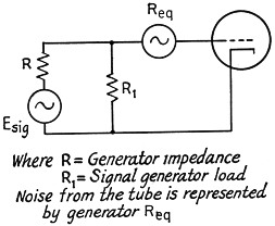
Fig. 3.
![]()
The first term on the right side of this`equationJgives the effect upon the noise figure of a load upon the source of voltage when tube noise is disregarded. Such a load produces noise but no signal; thus, if R = R1 this term in the equation is 2. The second term shows the effect of the load upon the source in reducing the voltage in comparison with the noise voltage contributed by Req. If R = R1, the second term of the equation becomes 4Req / R.
When Req is about the same in value as R or larger, the second term is, of course, larger than the first term and has a greater influence on F. Under these conditions, changing from the actual antenna to a dummy may cause a change in R which could swamp out the effect of any external noise present in the antenna.
Now let us consider the simple teat prescribed to determine whether or not the receiver is noisy. If we take the assumption made by the authors that we are operating at a frequency where external noise is very low, there is no reason that substituting a dummy antenna for a real antenna should reduce the noise, since the radiation resistance of the antenna certainly would not have a temperature greater than that of the dummy resistance. If there were actually no external noise, this test could condemn the best receiver that could be built. The fact that very few amateurs have the equipment to measure the impedance of an antenna also makes it very difficult to assess the reason for the change in noise level when the dummy antenna is substituted for the real antenna. As shown above, with a change in impedances between the two it is quite conceivable that the noise level could increase when the resistor is substituted for the antenna.
As mentioned in the article, a low-noise-figure receiver has no advantages in a noisy location, so another simple test can be prescribed to see if the receiver is working down to the local noise level. The receiver should be set to a frequency where there are no signals and the antenna trimmer should be tuned through resonance. If there is an increase in noise as the antenna circuit goes through resonance, the receiver is satisfactory for the location. If no noise peak is noticed then some improvement is called for.
If we are to make some improvement in the receiver it is nice to know where to begin. Now we remove the antenna and swing the antenna trimmer through resonance. If we hear the noise peak there is hope that the necessary changes will not be too drastic. Perhaps in this case a new r.f. amplifier may be the answer. If we hear no change in noise, the next step is to vary the trimmer on the next grid. If a change of noise is heard, there is still hope that the receiver can be improved. If no change of noise is heard in this case, I can only recommend a new receiver or a converter.
Assuming that we have decided that we need a new r.f. amplifier, let us look into the question of what is the best type of amplifier to use. To make our calculations easier, assume that we match the antenna into the receiver, a condition which is necessary if we are to have a flat transmission line feeding the receiver. Because of tracking difficulties most receivers covering wide tuning ranges will not be more closely coupled than a matched condition. This matched condition will give us a noise factor at least 3 db. worse than we would have if we had no loss in the antenna transformer and maintained the same source impedance feeding the tube.
We should now look again at equation (1).
As stated by Goldberg, we should take the sum of the Req1 + Req2 for the two tubes in a cathode-coupled circuit. For simplicity, let us neglect the two cathode resistors in the circuit, which will further degrade the noise performance of the amplifier, and just assume that if there is a close contest between the cathode-coupled amplifier and one of the others, it would be advisable to select the other one. Although the authors have selected the 6AC7 as a high gm tube they have proceeded to bias it until the gm is down to about 4000 µmhos.
In our calculations let us consider two receivers, one with a very good input circuit which, when loaded by the antenna, offers a source impedance R of 5000 ohms to the r.f. amplifier and the other a relatively poor one which offers a source impedance of 500 ohms to the first tube. We can now look into the noise figures of four different amplifiers: a 65K7, a 6AG5, the cathode-coupled stage recommended in the article, and a 6BQ7 cascode circuit. The noise resistances for these follow:
| 6SK7 | 11,000 ohms |
| 6AG5 | 1650 ohms |
| 6C4 | 800 ohms |
| 6AC7 triode with 1500 ohm cathode resistor | 600 ohms |
| 6BQ7 | 500 ohms |
Goldberg gives the following formulas for the noise figures:
Grounded cathode:
![]()
Cathode coupled:
![]()
Inserting numerical values we have:
| R = R1 = 10,000 ohms | R = R1 = 1000 ohms | |||
|---|---|---|---|---|
| F (power) | N.F. (dB) | F (power) | N.F. (dB) | |
| 6SK7 | 6.4 | 8.1 | 46 | 16.6 |
| 6AG5 | 2.66 | 4.25 | 8.6 | 9.35 |
| 6C4-6AC7 cathode-coupled | 2.56 | 4.10 | 7.6 | 8.8 |
| 6BQ7 cascode | 2.2 | 3.4 | 4.0 | 6.0 |
From these figures it can be seen that very little is gained by going to a system more sophisticated than the 6AG5 pentode unless R is very low and in this case it seems worth going to the cascode which is really a simpler modification than the one recommended in the article in question.
On the basis of the considerations above, I recommend that anyone contemplating the modification of a receiver give the situation a lot of study before he digs in with the cutting pliers; and it is my opinion that the modifications recommended in the article are not the easy way to improve a receiver.
W.B. Bernard, K6EUS, Cmdr., USN.
Technical Editor, QST:
Whilst the writer can fully agree in principle with the findings of Longerich and Smith in their article on low-noise receiver design, it seems that they have taken the long way round the problem.
The 6J6 has an equivalent noise resistance of 470 ohms,(1) and lends itself to use in the circuit shown in Fig. 1, which is electrically identical to that used by your contributors in their r.f. stages.(2)
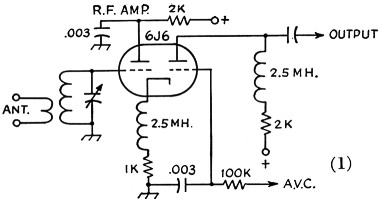
Fig. 1.
One of the advantages of this circuit is its ability to handle signals of several volts; yet it is reasonably free from cross-modulation effects. This is because the total plate current is almost constant when the control voltage is varied. For example, a drop in the grounded-grid section plate current caused by a.v.c. lowers the bias to the cathode-follower section, which in turn increases the plate current in that section. It follows then that the cathode-follower section is unimpaired by a.v.c. bias and may handle a signal input of several volts. The degree of curvature of the grounded-grid section then determines the degree of cross-modulation. The stage gain compares more than favorably with ordinary r.f. pentodes, and it may have a.v.c. applied.
Mixer tracking, instability and oscillator pulling difficulties experienced by the authors were to be expected under the conditions of nonisolation used. A mixer capable of good gain (approximately 14 times at 30 Mc.) with quiet operation is shown in Fig. 2.(2) This circuit has good isolation from the oscillator. Circuit gain is independent of oscillator injection-voltage change.
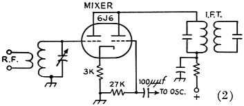
Fig. 2.
An alternative oscillator to that used by the authors is shown in Fig. 3. This circuit overcomes switching difficulties since there is no cathode tap nor are there two coils to switch as in pentagrid circuits. The cathode output gives splendid isolation from the mixer and pulling troubles are virtually eliminated.
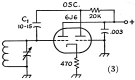
Fig. 3.
Feed-back control is by means of C1, which should be a silver mica for best stability. The value shown for C1 is satisfactory for operation over the range 3.5 to 50 Mc., but for operation at i.f. requires a feed-back condenser value of 100 pF or larger, depending on the i.f. This circuit makes an excellent b.f.o., since any old i.f. transformer will suffice for the grid inductance, no tap being required. All these circuits have been tried and are in use in the writer's receiver. They are simple to adapt into existing commercial receivers, requiring only a socket change and realignment. Manufacturers seem to have overlooked these triode circuits, and it would be worth their while to experiment with them.
Notes
- Radiotron Designer's Handbook, 4th ed.
- Philips Valve Data Book, Philips Electrical Industries of New Zealand Ltd., Vol. 3, ECC91-2-3.
R.S. Pottinger, ZL4GP.
Technical Editor, QST:
In the March issue of QST Longerich and Smith discuss low-noise receiver design. The r.f. input circuit shown is a cathode-follower amplifier followed by a grounded-grid stage. I believe their interpretation of the performance of this combination is somewhat misleading, in that it seems that they assume that the low-noise performance of the grounded-grid amplifier is not spoiled by the preceding cathode follower, or grounded-plate amplifier, and in fact, no thought seems given to the choice of a triode of low-noise resistance for the cathode-follower stage, since a Type 6C4 tube is used. The noise resistance of a 6C4 is 1140 ohms compared with 220 ohms for a triode-connected 6AC7. The combination used by the authors would be somewhat inferior to a low-noise design using a single pentode-connected grounded-cathode amplifier employing a Type 6AC7 tube.
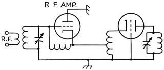
Fig. 1.
Basically, the circuit used by the authors is a grounded-plate grounded-grid triode amplifier. The conventional circuit is (simplified):
Here neutralization of the first stage is required except perhaps for the case where triode-connected pentodes are used.
The cathode interstage coupling coil is designed to present optimum admittance to the grounded-grid tube for minimizing the noise figure of the second stage. To calculate the noise figure of this combination we need to calculate the noise contributions of the two tubes, and if for simplicity we assume the two noise figures are identical, the noise figure of the combination can be shown to differ little from that of the first circuit.(1)
If the tap on the interstage coupling coil is left out this circuit becomes the so-called "cathode-coupled amplifier" shown below:
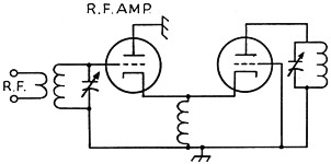
Fig. 2.
The noise figure of this combination is slightly poorer. Since the two triodes here are directly connected through their common cathodes, a valve often used in this circuit is a Type 6J6 (whose equivalent noise resistance is 470 ohms for each triode section). This circuit is identical to that used by Longerich and Smith, except that a.c. coupling is employed rather than direct coupling and the series-resonated coil in the cathode is replaced by a resistor. The noise figure of the cathode-coupled amplifier is in general somewhat better than the grounded-cathode pentode amplifier. This circuit is, however, inferior to the grounded-cathode grounded-grid triode circuit in both noise figure and stability (i.e., the so-called Wallman circuit(2) or cascode r.f. amplifier(3)). Also, the lower available power gain of the grounded-plate triode means that contributions of third-stage noise are correspondingly greater.
Notes
- Valley and Wallman, Vacuum tube amplifiers, p. 664 (McGraw Hill M.I.T. Radiation Laboratory Series).
- Shimizu, "Modified Wallman circuit with voltage feedback," Electronics for Communication Engineers, p. 28 (McGraw Hill, 1952).
- The Radio Amateur's Handbook, p. 366 (1954).
Jack Belrose, ex-VE7QH-VESBLW.