An improved antenna bridge
Increased accuracy and convenience in impedance measurements.
Most earlier designs of simple variable-impedance bridges for antenna and other r.f. impedance measurements have been open to serious objections because of inherent inaccuracies. Described here is a circuit that overcomes these objections and offers greater convenience in operation. Also described is a balun of novel construction for eliminating errors in measurements on balanced lines and loads.
It is often desirable to determine the resistance and resonant frequency of an antenna, to check the standing-wave ratio on a transmission line, to find receiver-input impedance, and to make many other r.f. impedance measurements. The antenna bridge described here offers an improved means for making these measurements, and at the same time is simple in design and easy to construct and use.
Fig. 1A is the fundamental circuit of a standard Wheatstone bridge. Fig. 1B shows two adaptations of the Wheatstone bridge for radio-frequency measurements; the similarity between these diagrams and the basic d.c. resistance bridge is obvious. In the development of such bridges, a subsequent step was that of using the adaptation in Fig. 1B to make a fixed-impedance standingwave-ratio bridge. The schematic circuit diagram of such a bridge is shown in Fig. 3C. R4 can be a 51 ohm carbon resistor for 50-ohm coaxial line. The two ratio arms consisting of R2C2 and R3C3 are identical so that the bridge unbalance is minimum when the impedance connected to the output jack is equal to 51 ohms and is a pure resistance. If the impedance differs from 51 ohms the meter reading will not be zero and the instrument can be calibrated either in terms of impedance or standing wave ratio. However, at impedances other than 51 ohms, the accuracy of measurement frequently is not too good.(1)
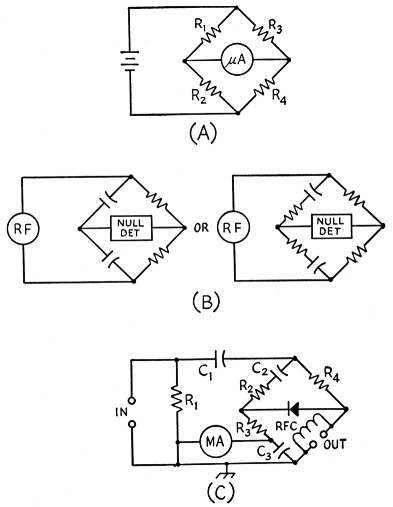
Fig. 1. The basic Wheatstone bridge (A) and adaptations (B) for r.f. use. (C) is a typical practical circuit for a bridge with fixed-resistance arms. C1, C2 and C3 in this circuit are blocking capacitors.
In an attempt to avoid being restricted to a fixed impedance, bridges have been made using a potentiometer in one arm. This seems like an obvious solution, but there are several disadvantages to this type of bridge. Principally, there is a substantial frequency error because a potentiometer is not a pure resistance but a combination of resistance and reactance, and as the arm of the potentiometer is moved, the ratio of resistance to reactance changes. Hence the accuracy of measurement is relatively poor and the calibration depends on frequency. Thus the substitution of a potentiometer in the simple fixed-resistance bridge is not too good a solution.
A disadvantage of bridges using all resistance arms is that the r.f. power requirements, while not large in terms of watts, are often greater than can be supplied by a grid-dip meter. It therefore becomes necessary to use a transmitter to supply the power, but since even a low-power transmitter generally has an output sufficient to overload the bridge components, some provision must be made for reducing the power to the proper level. A grid-dip meter would be a more convenient power source.
A circuit suggested by S. W. Seeley, W2ZE, offers the possibility of very considerable improvement in both respects. In this arrangement a differential capacitor supplies the variable components of an adjustable-impedance bridge, and since capacitance can be measured much more accurately than resistance at r.f., and can easily be kept "pure" at ordinary frequencies, a high order of bridge accuracy becomes possible. A differential capacitor is a dual capacitor so arranged that as the shaft is turned the capacitance of one unit decreases by the same amount that the capacitance of the other increases; in a bridge, the two capacitors become the variable ratio arms. The practical form of W2ZE's circuit is shown in Fig. 2, where C1 is the differential capacitor. C1 does not use up any of the r.f. input power, and when a microammeter is used as an indicator, the circuit will operate well from a grid-dip meter source even with loose coupling.
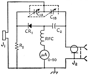
Fig. 2. Bridge circuit using differential capacitor for adjustment of impedance ratio.
| C1 | Differential capacitor, 11-161 pF (Millen 28801). |
| C2 | 0.01 µF disk ceramic. |
| R1 | 1 ohms, 2 watt composition, 5% tolerance. |
| J1 | Crystal socket. |
| J2 | Coaxial connector. |
| RFC | Miniature choke, 200 µH, iron core (Millen J300-200). |
| CR1 | Germanium diode, 1N34A suitable. |
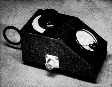
The simplicity of the bridge is evident from its appearance. The unknown impedance to be measured is connected to the coaxial jack on the side, and r.f. from a grid-dip meter is coupled to the loop at the left.
The only fussy part of the bridge is the differential capacitor. For compactness and reduction of stray effects this capacitor, like the one shown in the accompanying photograph, should be designed especially for the purpose. Two identical single capacitors, ganged together so that one is at maximum when the other is at minimum capacitance, may be usable; however, the frequency error will be greater even though the assembly is kept as compact as possible to minimize stray inductance.
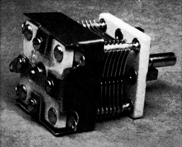
The differential capacitor which is the heart of the bridge circuit. The copper shielding fastened to the rear end plate is to prevent stray coupling to other components in the bridge.
Construction
The photographs show the construction of a bridge built to W2ZE's design. As can be seen by looking at the inside view, the unit is not at all complicated; however, it is advisable to stick to the suggested components and layout. Obviously it is undesirable to have unnecessary lead inductances or capacitances between bridge arms. As shown in the inside view of the bridge and in the photograph of the differential capacitor, a copper shield is placed around the top part of the capacitor to shield the stators from the other elements of the bridge. Since the calibration accuracy at the upper end of the frequency range is limited by stray capacitances between bridge elements, the addition of this shielding raises the upper frequency limit at which the bridge maintains its accuracy. With the shield around the condenser the frequency error is very small up to at least 50 Mc.
The choke in the bridge is a miniature powdered-iron-core layer-wound solenoid. The lead between the coaxial input connector and the capacitor is a short piece of flat copper ribbon. Any revision in the layout that results in longer leads will tend to result in increased frequency error.
The Type 1N34A germanium diode was used because it is satisfactory and because it is generally available. Other types should be equally satisfactory, however.
R.f. is introduced into the bridge circuit through the crystal socket shown at the bottom of the unit in the inside view. Three plug-in pick-up loops are used for coupling the output of a grid-dip meter to the bridge. These coils have 1, 3 and 10 turns, respectively, and are mounted on Millen 37412 300-ohm transmission line plugs. The 10 turn coupling coil, which is 1M inches in diameter, resonates in the bridge over the approximate range 5.2 to 8.8 Mc., depending on the impedance (that is, capacitor) setting. The 3 turn coupling coil, also 1% inches in diameter, resonates from 15.5 to 30.5 Mc. and the 1-turn coupling coil (1 inch in diameter) resonates from 32 to 84 Mc. With the bridge set to 50 ohms the 10-turn coil and the 3 turn coil result in the same coupling at 12 Mc.; consequently, the 10-turn coupling coil should be used for measurements below 12 Mc. The 3 turn coil and the 1 turn coil result in approximately the same coupling at 40 Mc.; consequently, the 3-turn coil should be used for measurements between 12 and 40 Mc. and the 1-turn coil should be used above 40 Mc. In general, the coupling coil closest to resonance at the particular capacitor setting in use should be chosen. It is, of course, possible to make coupling coils that will be resonant at the particular frequency for which a measurement is desired, but experience has shown that the three coils suggested cover the range adequately. Other coils would be required only under certain very special circumstances.
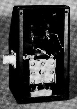
Inside view of the bridge. Components are easily identified with the possible exception of the miniature choke, which is mounted between the left-hand meter terminal and the junction between the 1N34A and the ceramic blocking capacitor.
The 3 turn coupling coil was made by threading the 3 turns through a piece of spaghetti cut to the proper length. The 10 turn link can be wrapped in insulating tape and thoroughly doped in coil cement, or the coil can have a coating of vinylite built up on it by repeated dipping in liquid vinylite material which is readily available for caulking and waterproofing. This material apparently has no harmful effect upon the coils.
Calibration
The theoretical calibration of angular setting of the capacitor rotor vs. impedance is a shallow S-shaped curve, when plotted on semilog paper, symmetrical with respect to the design center impedance. The curve for the bridge described here is shown in Fig. 3.
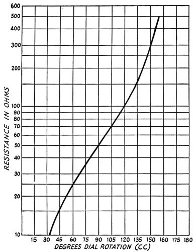
Fig. 3 - Calibration curve of the bridge shown in Fig. 2 and the photographs.
A similar curve can be constructed for a given bridge by connecting carbon resistors of various values between 5 and 500 ohms to the output connector and adjusting the capacitor for a null in each case, using a calibrated grid-dip meter as the source of an r.f. voltage of known frequency. A similar procedure at various frequencies within the range of the grid-dip meter will show whether there is any appreciable frequency error, and if so, the frequency at which it tends to become important. Lead length between the body of the test resistor and J2 should be kept to a minimum, particularly with the lower resistance values.
For highest calibration accuracy the test resistors should be measured with an accurate resistance bridge or ohmmeter so their actual resistance is known. If suitable instruments are not available for measuring the resistances, resistors having 5 per cent tolerances or less should be used.
Applications
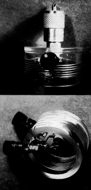
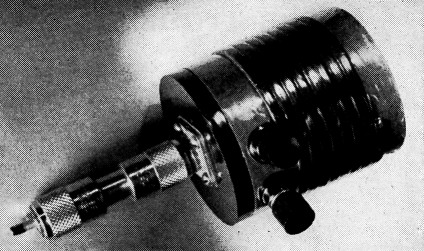
Two views of the wound balun. This circuit covers the 10-20-meter range. Similar baluns for other frequencies may be designed and constructed by the method outlined in the text.
When used with coaxial lines or other loads that can have one side grounded, the bridge is applied to amateur antenna and impedance problems in exactly the same way that the older-type bridges, both fixed and variable, have been applied. Since this subject has been very adequately covered in amateur publications, we will add only a few notes here. The only real difference between this and the previous instruments is the ease with which measurements can be made and the improved accuracy. The r.f. input to the bridge is not critical, but with a 50-microampere meter movement such as is used in the circuit shown, the measurements should begin with loose coupling to avoid the possibility of damaging the meter. Actual use of the instrument is very simple and in general the procedure for measuring impedance is as follows:
- Couple an r.f. voltage of the desired frequency to the bridge.
- Adjust the coupling by moving either the bridge or the r.f. source so that the meter indicates about 40 microamperes.
- Connect the unknown impedance to J2.
- Adjust the dial for minimum meter reading.
- Read the value of the unknown impedance from the calibration.
In this connection, it should be noted that the impedance being measured may not be a pure resistance, in which event the minimum reading will not be an actual null. If a good null (meter reading zero or very close to it) cannot be obtained, the bridge calibration does not hold. (This is true of any bridge circuit which does not incorporate special means for separating the resistive and reactive components of the unknown impedance.) Conversely, a complete null does indicate that the unknown impedance is a pure resistance. With complex unknowns, the reactive component can be tuned out by one of a number of well-known methods, leaving only the resistive component to be measured by the bridge. In such a case, the criterion for proper reactance compensation is the fact that the null is complete.
For s.w.r. checks the bridge capacitor should be set to the calibration point corresponding to the characteristic impedance of the coaxial transmission line in which the s.w.r. is to be measured. This setting should be left unchanged during any subsequent adjustments to matching devices, the object being to adjust the matching circuit to obtain the lowest possible reading on the meter. As is usual, a complete null indicates a 1-to-1 standing-wave ratio.(2)
Balanced lines or loads may be measured with the bridge by using a circuit that provides suitable balanced-to-unbalanced coupling between the bridge and load. The wound balun devised by W2ZE and described below is a very convenient form of such circuit.
The Wound Balun
A wound balun is simply an accurate 2 to 1 auto transformer with the residual reactances tuned out and as tight coupling as possible between the two halves of its total winding. If the impedance is measured between a grounded center-tap and one terminal of the winding when a balanced load is connected across it, the 2 to 1 turns ratio produces a 4-to-1 step-down in the impedance measurement. For example, a properly-terminated balanced 600 ohm line connected to the outside terminals of the winding would be measured as 150 ohms between the grounded center-tap and either end. This means that the readings of the antenna bridge must be multiplied by four when using the balun. Thus the range of a 5-500 ohm bridge becomes 20-2000 ohms for balanced loads. This coincides with the usual higher impedances of balanced lines. Use of a balun maintains balance during measurement and thus obviates the wild errors usually encountered when one tries to measure any balanced-line impedance without first converting it to a single-ended load.
A balun for 40 and 80 meters, using 150-ohm Twin-Lead (Amphenol 14-079 or Alpha 1151) for the bifilar winding. There are 8 turns of Twin-Lead on 2¾ inch diameter bakelite tubing. The shunt tuning capacitance for 80 meters is 62 pF; no shunt capacitor is needed for 40 meters. The series capacitance for 80 meters is 0.0045 µF and for 40 meters is 0.001 µF.
This model uses a female coaxial connector, which accounts for the double-ended male connector shown in place.
There are five principal requirements for the construction of an accurate wound balun:
- The two halves of the winding must be as nearly equal and as symmetrically positioned as possible.
- The coupling between the two halves of the winding must be as close to 100 per cent as possible.
- The Q of the winding must be high.
- The total inductance must be resonated to the frequency of operation by a shunt capacitor across the balanced terminals.
- The residual leakage reactances should be tuned out by means of a capacitor in series with the "hot" single-ended terminal.
These five objectives are accomplished in the following manner:
Symmetry and tight coupling, (1) and (2), are obtained by making the two halves of the winding bifilar. In the 10-20 meter balun illustrated the 2 inch diameter lucite form is wound with its 3 turn windings paired in double-thread, 7 t.p.i. lathe-cut grooves. In winding, the wire starts; at the beginning of one thread, continues for three turns to the end of that thread, goes through a hole to the inside of the form, back:. to a hole leading out to the start of the second thread, then continues in that thread for three more turns to the end of the winding. The center of the wire, where it goes from the end of the first thread to the beginning of the second, is the exact physical (and electrical) center of the two windings. That point is joined by a short, heavy strap directly to the body of the male coaxial connector.
The Q of the illustrated balun turned out to be 235 at 14.3 Mc., which is the equivalent of about a 50,000-ohm resistor in shunt with the balanced load to be measured. This causes an error of about 4 per cent in the reading of a 2000-ohm load but only 1 per cent for a 500 ohm load.
When this balun was tuned to operate at 28 Mc., it showed almost exactly the same shunt resistance. Several transmission-line baluns that were tried showed four to five times the error of this wound balun due to their lower Q.
Tuning out the residual reactances of the wound balun can be done rather easily with the aid of a grid-dip meter. The problem is somewhat simplified if one first calculates the amount of capacitance required to resonate the total winding to the center of the frequency band in which it is to be used. In the case of the illustrated balun, the Lightning Calculator indicated 2.6 µH which would require a total capacitance of 49 pF. to resonate it to the center of the 20 meter band. It was estimated that the coil distributed capacitance would be about 10 pF so a fixed 39 pF. ceramic was connected across the balanced terminals. The grid-dipper then showed resonance at 14.3 Mc., which was plenty close enough.
At first it was thought that the small residual leakage reactances could be tolerated without a correcting condenser in series with the single-ended output. But it turned out to be such an easy job to find the correct value and put it in, and the increased accuracy thus gained was so immediately apparent, that it seems well worth while to include it.
As a starter, it was assumed that the leakage inductance of the coil and leads would be somewhere in the neighborhood of 2 to 3 per cent of the total coil inductance. This would take a capacitor 30 to 50 times larger than the total tuning capacitance to counteract it. So a 0.002 µF capacitor was placed in series with the single-ended output terminal (stud of the coax connector) and the end terminal of the coil. Then the two binding posts were shorted with a piece of straight, round wire and the coax connector was plugged into a shorted female connector. The grid-dipper then showed resonance at 12.3 Mc. This indicated that the capacitor was about 30 per cent larger than it should have been so it was replaced with .0015 µF (1000 pF and 470 pF in parallel shown in the photograph). A grid-dip check with both input and output shorted then showed resonance at 14.6 Mc., again amply close.
The same balun turned out to require 4 pF (plus the 8 pF distributed) for shunt tuning at 28 Mc. and the series capacitor was 420 pF. A 10 per cent error in the value of either of these capacitors is relatively unimportant. With the values indicated for 14.3 Mc., errors caused by the balun itself were so small as to be unreadable when used with a bridge such as the one described in this article (well below 1 per cent if the 50,000-ohm shunt-coil losses were used to determine a correction factor).
Omission of the leakage-reactance correction capacitor made quite a sizable error when measuring loads of 100 ohms or less at 28 Mc. Inclusion of the capacitor reduced these to less than 2 per cent for any value.
As mentioned previously, the 1000 pF and 470 pF forming the 0.00147 µF series capacitor for 20 meter operation are shown in the illustration between the outer terminal of the winding and the center stud of the connector. Either tuning capacitor (4 pF for 10 meters or 39 pF for 20 meters) can be connected externally across the binding posts.
When using the balun for 10 meters, the 1000 pF portion of the series capacitor is opened.
In conjunction with the bridge, the balun described can be used over a ±500 kc. range on 20 meters and ±1 Mc. on 10 meters, without retuning.
Conclusion
The simple antenna bridge described here can be used for almost any type of r.f. impedance measurement that the amateur is called upon to make. The possibilities in this regard have only been touched upon in this article, but the many applications have been well covered in amateur literature. There is only one warning - do not, under any circumstances, leave the bridge in the circuit while the transmitter is in use. The bridge is a measuring instrument, not a device for monitoring the performance of the transmitter.
Notes
- This is partly because the accuracy of such a bridge tends to decrease, as a practical matter, with an increase in the ratio of the impedances in the unknown and standard arms. Also, as has been pointed out many times in QST and the Handbook, for accurate measurement it is essential that the indicating circuit have good linearity and extremely high impedance compared with the bridge impedance, and that the r.f. input voltage be maintained constant when the load is disconnected or short-circuited for the reference voltmeter setting. - Ed.
- Although the factors mentioned in Footnote 1 do not affect the accuracy of impedance measurement with the bridge described, since the bridge is always adjusted for a null in such measurements, they do apply with full weight to the measurement of standing-wave ratios higher than 1 to 1. For s.w.r. measurement, provision for checking the input voltage should be included in the circuit of Fig. 2, and a resistance of at least 10,000 ohms - preferably as much as 50,000 - should be placed in series with the microammeter. However, these precautions are not necessary for purely qualitative comparisons nor for facilitating matching-circuit adjustments where the object is to attain the lowest possible meter reading. Most amateur uses of an s.w.r. bridge are in this category.- Ed.
R. Wade Caywood, W1KRD.