The transistorized "little gem"
A versatile r.f. and d.c. meter.
Almost 10 years ago (January, 1946) QST carried a description of the "Little Gem," an absorption-type wavemeter that doubled as phone monitor and field-strength indicator. By adding the gain of a transistor d.c. amplifier stage, the sensitivity of the gadget is increased considerably, and what is normally a milliammeter becomes a microammeter. This will he found to be a handy and useful instrument to have around the shack. Once you have used it you will see why it is called the "Little Gem."
The high cost of transistors has limited transistor use in amateur radio. Recently, however, low-cost transistors have been made available, and we can expect to see them in frequent use. Since the transistor is very small, light in weight, rugged and easily powered by a small pen-light cell, its logical application is to portable equipment. The above advantages obviously add up to the transistor's application to portable measuring devices for the ham. The instrument described here can be used in five different ways: field-strength meter, wavemeter, microammeter, milliammeter, and 'phone quality monitor. It is a "natural" for mobile work as it can be carried about without restricting wires or bulky batteries.
The transistor in this unit operates as a current amplifier to Multiply the input signal to a value high enough to be indicated on a 0-1 milliammeter. This allows a less expensive and, more rugged milliammeter to be used instead of the usual expensive microammeter.
The diagran of Fig. 1 shows the circuit of the instrument. When used as a field-strength mater or a wavemeter, the signal from the source to be measured is received by the antenna and tuned by L1C1. It is then rectified by the crystal diode and impressed on the transistor where it is amplified and indicated on the meter. Since the transistor inherently has a static collector current under no-signal conditions, some means must be provided to electrically balance or zero the meter. This is accomplished by adjusting the variable resistance, R1. If the signal being measured is very strong, no external antenna will be necessary for full-scale deflection. When more sensitivity is needed, a short piece of stiff wire can be connected to the antenna binding post.
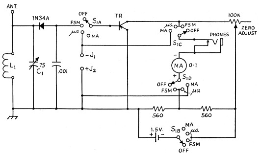
Fig. 1. Schematic diagram of the transistorized "Little Gem." All resistors ½watt.
| L1 | 1700-3000 kc.: 100 turns No. 30 enam., close-wound on ¾ inch form 3300-7600 kc.: 32 turns No. 30 enam., close-wound on ¾ inch form 12-30 Mc.: 13 turns No. 20 enam., ¾ inch form, spaced diameter of wire 30-80 Mc.: 3 turns No. 20 enam., ¾ inch form, spaced diameter of wire 40-110 Mc.: short loop of No. 10 enam. (plugged directly into coil socket) All coils are wound on Amphenol 24-5H forms. |
| C1 | 75 pF midget variable condenser (Millen 20075) |
| S1 | 4 pos. 4 pole miniature steatite rotary switch (Centralab PA-2011) |
| J1,J2 | Nylon tip jack (Johnson 105-602-1) |
| TR | PNP junction transistor (Hydro-Aire CQ-1) |
If it is desired to check the quality of a phone signal, it is only necessary to plug a pair of headphones into the 'phone jack. The closed-circuit jack isolates the meter from the circuit and allows the amplified audio component of the rectified signal to be heard.
When the instrument is to be used as a micro-ammeter, the transistor is switched from the diode rectifier circuit to polarized pin jacks mounted on the cabinet. The transistor continues to operate as a current amplifier, and full-scale deflection can be obtained with a very small current flow at the input. Since the basic movement of the meter is 0-1 mA, switching is provided to isolate the meter for milliampere readings. The two pin jacks used for microampere readings are also used for measuring milliamperes.
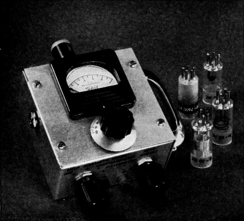
The transistorized "Little Gem" with plug-in coils which provide coverage of all amateur bands, 160 through 6 meters. The phone jack is mounted on the side of the cabinet and insulated by fiber washers.
Construction
The unit is constructed in a 4 × 2 × 4 inch utility cabinet. Placement of the components is not critical for operation, but some care must be exercised because of space considerations. The meter and the tuning control, CE, are mounted on the removable front plate. Since the meter is mounted at the very top of the face place, some of the lip on the box will have to be removed to allow the meter to fit properly. Function s witch, zero adjust control and pin jacks are all mounted on one end of the box, with the coil socket and antenna post on the other. The 'phone jack and holding handle are secured to opposite sides of the box. The handle on this unit was placed for a left-handed person but it can be mounted on either side. The transistor is supported by its own leads, and great care must be exercised in soldering because an excess of heat will permanently impair its operation. It is good practice to hold the leads of the transistor with long-nose pliers while soldering so the heat will flow into the pliers and not the transistor. A small pen-light cell is used to power the transistor and it is supported by soldering the plus terminal of the cell to the tie-bolt of the switch assembly. The negative or case side of the cell is not supported and the lead to it is soldered to the bottom of the cell. Plug-in coils for the unit are wound on Amphenol miniature plug-in coil forms which require a special socket (Am-phenol 78-S5S). The range of the coils in this set covers 1700 kc. to 120 Mc. If it is desired to include the 144-148 Mc. band, a smaller tuning capacitor should be used.
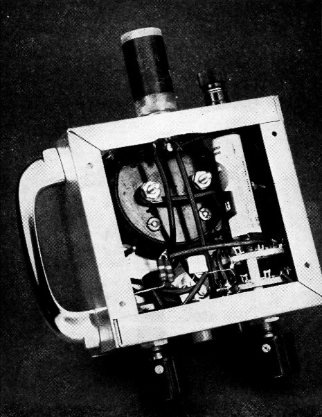
Bottom view showing placement of components. The transistor can be seen at bottom center supported by its own leads. The pen-light cell is supported by soldering the plus cap to the switch tie bolt.
Operation
To use the instrument as a field-strength meter or micro-ammeter, the function switch is turned to the desired position and the meter is balanced by rotating the zero adjust control until the pointer is set on zero. The meter is now ready for use and no further adjustments are necessary. To measure the strength of a signal, the tuning control is turned until the maximum reading is found. Once the tuning control is set, relative strength measurements can be made for different antenna conditions. A calibration chart of the dial settings at different frequencies can be made and placed on the back cover plate of the box, and the instrument used as an indicating wavemeter. The chart can be calibrated by the use of a grid-dip meter or VFO. It might be well to remember that the calibration (when used as a wavemeter) will change slightly if an external antenna is used. When microampere measurements are being made, test leads are plugged into the pin jacks and the meter is used like any standard microammeter. Care should be taken not to use the instrument in circuits where the current will deflect the meter over full scale. The amount of amplification that the transistor will have depends on the partitular transistor used. The transistor in this unit was found to have a current gain of 20, or 26 dB, so that full-scale deflection on the 0-1 mA meter was 50 µA. To calibrate the meter for microammeter measurements, a simple calibration circuit can be set up using a dry cell and several known resistances. A diagram of the circuit is shown in Fig. 2. Currents that will flow in the circuit with given resistances are also shown. By the use of Ohm's law any current flow through the circuit can be calculated if the resistance and voltage are known. By plugging in a pair of headphones and setting the function switch on field strength meter, the quality of a 'phone signal may be observed. The transistor is acting as an amplifier in this position, so the gain will be more than enough for strong headphone volume. This feature will be appreciated when monitoring a mobile 'phone signal, where the signal strength is low.
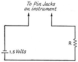
Fig. 2. Microammeter-calibration circuit using known resistances and voltage. By using a 1.5 volt cell and known resistances R, current I will flow in the circuit. Naturally, the closer tolerance resistors will give more precise calibrations.
| R (ohms) | I (µA) |
|---|---|
| 150,000 | 10 |
| 68,000 | 22 |
| 47,000 | 32 |
| 33,000 | 45 |
| 18,000 | 83 |
| 15,000 | 100 |
The basic movement of the meter in this instrument may be used by switching the function switch to milliammeter. Leads are connected to the pin jacks and the instrument is used accordingly. External shunts may be used with the basic 0-1 mA movement to provide an extremely wide range of current measurement.
A PNP junction transistor was used in this unit. However, a NPN type may be used if the cell, meter, and tip-jack leads are reversed.
E. Laird Campbell, W1CUT.