807s in parallel
75- to 150 Watt amplifier with Pi-section output.
Judging from our mailbag, the greatest demand in transmitters these days is for a job running at 100 to 150 watts input. This parallel 807 job fills the bill quite simply and inexpensively.
The amplifier shown in the photographs was designed to cover all bands from 3.5 to 30 Mc. It can be operated at an input of 150 watts on c.w., or 120 watts on phone. However, it will operate efficiently at 75 watts input for Novice use.
Circuit
A pair of 807s in parallel is shown in the circuit diagram of Fig. 1. A pair of 1625s may be substituted if a 12.6 volt filament transformer is provided.
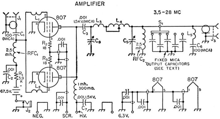
Fig. 1. Circuit of the parallel 807 amplifier.
| C1 | Not needed if driver has output coupling capacitor. |
| C4 | 250 pF 1200 volt variable (National TMS-250 or TMS-300, Bud CE-2007 or similar, 0.03 inch plate spacing). See text. |
| C5 | 250 pF or larger. See text. For low-impedance output, receiving spacing adequate. (Johnson 140R12, Bud MC-1860, MC-909 or MC-910, Hammarlund RMC-325-S, MC-250-M or MC-325-M). |
| L1,L2 | 22 turns No. 30 enam., ¼ inch diam., 7/16 inch long. |
| L3 | 3 turns No. 10, ¼ inch diam., ¾ inch long (see text). |
| L4 | Rotary inductor (see text). |
| L5 | See text. |
| J1 | RCA-type shielded phono jack. |
| J2 | Closed-circuit phone jack. |
| J3 | Coax connector. |
| S1 | Progressively-shorting rotary switch (Centralab P-121 index head, PIS wafer). |
All capacitances less than 0.001 µF are given in pF.
All fixed capacitors disk ceramic unless otherwise specified.
All resistors ½ watt unless otherwise indicated.
The amplifier is capacitively coupled to the driver through the 100 pF mica capacitor, C1. (If the driver includes an output coupling capacitor, Ci may be omitted, of course.) Li and L2 are small inductors which, in conjunction with R2 and R3 in the screen leads, are used for the suppression of v.h.f. parasitics.
A combination of battery and grid-leak bias is used. Since the screens are operated from a low-voltage source, the fixed bias provided by the battery will cut the input to the 807s to zero when excitation is removed, as in keying preceding stages for c.w. operation. When the screens are supplied through a dropping resistor from the plate supply, as required for plate-screen modulation, the battery will hold the input to a safe level in case of excitation failure, although the input will not be reduced to zero.
A pi-section tank circuit is used in the output, and parallel plate feed is therefore necessary. Either a rotary inductor from a surplus BC-375-E antenna-tuning unit or a Johnson type 229-201 inductor may be used as the variable inductor, L4. L3 is a separate inductor for 10-meter operation. It will not be needed if the Johnson inductor is used, or if the surplus inductor is used and 10-meter operation is not required.
The required output capacitance is furnished by a combination of a variable capacitor, C5, and several fixed capacitors that may be switched in parallel with the variable. A total of about 2000 pF. should be provided. For a continuous range of capacitance, each of the fixed capacitors should have a capacitance not greater than the maximum capacitance of the variable. As an example, a 500 pF variable and three 500 pF fixed capacitors may be used. A 250 pF variable, on the other hand, will require seven 250 pF fixed capacitors and a switch to accommodate them.
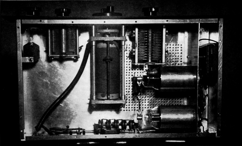
Top view of the parallel 807 amplifier. The variable output capacitor is at the upper left with the fixed mica capacitors and switch in the corner. The variable input capacitor is to the right of the variable inductor. The r.f. choke and by-pass fastened to the rear wall of the chassis are in the plate circuit. The biasing battery can be seen in the compartment to the right which also houses the input-circuit components. L3 and Cs were not used in this unit.
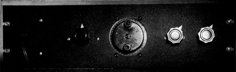
Panel view of the 150-watt amplifier showing the grid-meter jack, and controls for the pi-section input capacitor, variable inductor, variable output capacitor and fixed-capacitor switch.
RFC2 removes the d.c. plate voltage from across the input and output tuning capacitors, reducing the required voltage rating of these capacitors. It also provides protection against plate voltage appearing on the transmission line should the plate blocking capacitor, Ca, break down. In this event, RFC2 will short-circuit the plate supply. If the primary of the plate transformer is provided with a 3-ampere fuse, the supply will be protected.
C6 may be useful in localities where TVI is bothersome on one particular v.h.f. channel. In this case, the capacitor can be series-resonated to the particular channel by adjusting its lead length (represented by L5). It should be connected directly across the output coax connector.
Plate and grid milliammeters are not included in the unit, but are mounted externally on another panel to keep them out of r.f. fields. J2 is provided for plugging in a cord from the grid milliammeter while checking grid current. The plate meter is wired in permanently through terminals at the rear of the chassis. If desired, the jack can be omitted and the grid milliammeter wired in permanently, also.
Construction
An inverted 10 × 17 × 4-inch aluminum chassis is used as a shielding enclosure for the amplifier. A standard bottom cover is used as the top cover. The chassis and the cover are perforated in the area near the tubes to provide ventilation. Holes in addition to those provided are drilled in the cover and along the lips of the chassis so that the cover may be secured tightly to the chassis with No. 6 self-tapping screws. The chassis is centered behind a standard 5¼ inch aluminum rack panel.
The 807s are mounted horizontally from a partition spanning the chassis. This partition is made from a piece of aluminum cut 4_3/8 inches wide by 10 inches long. Half-inch lips are bent over at the front end and along the bottom edge for fastening it with machine screws to the front wall and bottom of the chassis. The partition is spaced 2 inches from the end of the chassis. The tubes are provided with aluminum shield cans, and the sockets placed sufficiently far to the rear to leave space for the input capacitor, C3.
Most of the assembly and wiring to the sockets can be done before the partition is fastened permanently in place. Pins 4 and 5 of each socket should be grounded right at the socket. The No. 2 pins are joined by the two resistors R2 and R3 in series. RFC1 is a National R-100-S, or similar model, with an insulating mounting. It is placed centrally between the two sockets and between the partition and the end of the chassis. It is eventually fastened against the bottom of the chassis. However, until the assembly is ready to be fastened in place, it is suspended by its leads. The two parasitic suppressor chokes, L1 and L2, are connected between the No. 2 pins on the sockets and the top of RFC1. If C1 is used, it should be connected between the top of the r.f. choke and the excitation input connector, J1. Otherwise, a short piece of wire should be substituted. The grid leak, R1, is mounted between the bottom end of RFC1 and an insulated tie point, and the grid by-pass, C2, is connected between the botom end of the choke and a ground on the partition. The negative terminal of the biasing battery is also connected to this tie point, while the positive terminal goes to J2.
| Band (Mc.) | 3.6 | 3.6 | 7 | 14 | 21 | 28 |
| 760 volts, 100 mA (3750 ohms) | ||||||
| Cin (pF) | 150 | 2301 | 75 | 38 | 25 | 20 |
| Cout (pF) | 910 | 1700 | 450 | 225 | 150 | 110 |
| L (µH) | 14.8 | 10.0 | 7.4 | 3.7 | 2.5 | 1.8 |
| 760 volts, 200 mA (1876 ohms) | ||||||
| Cin (pF) | 300 | 2502 | 150 | 75 | 50 | 37 |
| Cout (pF) | 1570 | 1160 | 785 | 390 | 260 | 195 |
| L (µH) | 7.9 | 9.3 | 4.0 | 2.0 | 1.3 | 1.0 |
| 600 volts, 160 mA (1868 ohms) | ||||||
| Cin (pF) | 340 | 2503 | 170 | 85 | 55 | 40 |
| Cout (pF) | 1680 | 1100 | 840 | 420 | 280 | 210 |
| L (µH) | 7.1 | 9.3 | 3.5 | 1.8 | 1.2 | 0.9 |
| 600 volts, 200 mA (1600 ohms) | ||||||
| Cin (pF) | 380 | 2504 | 190 | 95 | 63 | 47 |
| Cout (pF) | 1820 | 1000 | 910 | 455 | 300 | 227 |
| L (µH) | 6.4 | 9.3 | 3.2 | 1.6 | 1.1 | 0.8 |
| 1 Q=19 2 Q=10 3 Q=9 4 Q=8 All others Q=12 | ||||||
Three shielded and by-passed leads are prepared as described in the TVI chapter of the ARRL Handbook. One lead is connected to the junction of R2 and R3. The other two leads are fastened to the No. 1 pins of the sockets. After the partition has been fastened in place, the lead from the junction of the resistors should be connected to the screen-voltage input terminal. The other two leads both are run together to the ungrounded heater input terminal. The shields of these three leads are grounded at both ends, to each other, and to the chassis at several points.
The plate blocking capacitor, C3, is mounted with one of its terminals central in respect to the two 807 plate caps to permit plate leads of equal length. The parallel-feed plate choke, RFC3, is mounted off the rear wall of the chassis, with its cold end close to the high-voltage input terminal. The plate by-pass, C7, is fastened against the rear wall of the chassis, and is connected between the cold end of the r.f. choke and the high-voltage input terminal with the shortest possible leads.
The variable inductor cannot be mounted centrally in the chassis without interfering with the removal of the 807s. It is placed an inch or so away from the plate caps of the tubes, and the input and variable output capacitors are spaced symmetrically on either side. The fixed capacitors in parallel with C5 are stacked up and fastened to a grounding bracket attached to the left-hand end of the chassis. The front terminals of these capacitors are connected to the terminals of S1 mounted immediately in front.
Adjustment
The values of input and output capacitance and the value of the inductance to be used in the pi network will depend upon the voltage and current at which the amplifier is operated. For full input on c.w., a voltage of 750 at 200 mA is required for the plates, and 250 volts at 12 mA for the screen grids. In this case, screen voltage is best obtained from the exciter plate supply. For full input on phone, a supply delivering 600 volts at 200 mA is needed, and 275 volts at 13 mA for the screens. For phone work, the screen voltage should be taken from the plate supply through a 25,000 ohm 20 watt resistor.
For Novice operation, the amplifier can be operated, for instance, at 500 volts, 150 mA with both tubes in use, or at 750 volts, 100 mA with one of the tubes removed.
An accompanying table shows the values of input and output capacitance and the inductance required for a tank-circuit Q of 12 and 50 ohm output under the four operating conditions described above. The Johnson inductor does not have sufficient inductance for a Q of 12 under the 750 volt 100 mA condition. In this case, with maximum inductance in use, the Q will run around 17 or 18. Also, the values of input capacitance shown in the table include tube output capacitance and other stray capacitances, so that input capacitances of less than about 50 pF will probably be unattainable. Where the table shows less than 50 pF input capacitance, C4 should be operated as close to minimum capacitance as practicable.
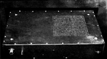
The amplifier is enclosed in an inverted aluminum chassis in which the bottom plate serves as the top cover. Along the rear edge are the output coax connector, ground post, tip jacks for heater, screen and plate voltages, and r.f. input jack.
An exciter should be connected to J1, and the coupling adjusted to give about 7 mA of amplifier grid current. With a 50 ohm load connected to the output, the input and output capacitances should be set as closely as possible to the values indicated in the table, and the variable inductor should be adjusted for resonance as indicated by the customary dip in plate current. Decreasing the output capacitance or the inductance (or both) while maintaining resonance with the input capacitor should increase loading. Adjustment in the opposite direction should decrease the loading.
Francis M. Yancey, K4CDO.