Power and meter facts in s.s.b. operation
Interpreting the linear-amplifier plate meter reading.
Here is some down-to-earth talk about linear amplifiers, power ratings and meter readings that is "must" reading for all s.s.b. enthusiasts. W1PNB presents the case in simple, nontechnical language and with illustrations that clearly demonstrate the basic principles.
Did you ever see an article mainly concerning the plate meters of final r.f. amplifiers? For that matter, have you ever given the subject much thought? Well, if not, it's certain that you have never used a linear amplifier in singlesideband suppressed-carrier operation. Of course, if you are a person with absolutely no aspirations toward s.s.b. in the future, you might be excused for saying, "Who cares?" However, the way things are progressing on the "Donald Duck" front, I think there are many who will be interested in the following material.
Why all the fuss about meters? In the days of regular a.m. there wasn't much concern. The d.c. plate meter gave most of the answers without complaint. Watch the meter. Tune up the rig. Figure the power input - no strain, no pain! What could be neater? To say that this no longer holds true with a linear amplifier in suppressed-carrier service would be quite an understatement. Strong men have wept bitter tears and spent sleepless nights because of the behavior (or misbehavior) of their linear's plate meter. Why? Simply because most of us seem to find it extremely difficult to modify our nearly complete, all-abiding faith in the value of the plate meter in indicating final amplifier performance.
Let's get down to brass tacks. The attitude of an amateur toward the plate meter of his linear final, under voice conditions, is of great importance. It could, from a broad point of view, mean complete success or partial failure of amateur narrow-band communication techniques.
Why does the d.c. plate milliammeter fall down so badly in indicating the performance of amplifiers in s.s.b. voice service? It's because the meter is no longer able to settle at a steady value as it did in the amplification of unvarying carrier signals. The voice modulation consists of sporadic bursts of energy. They say, "The hand is faster than the eye." If so, the voice is certainly faster than the meter. The meter just doesn't move rapidly enough. It starts to follow the first voice impulse up, but moves so slowly that it meets the signal coming down. Then it tries to follow down ward. In this it also fails. If a constant sound is used instead of words, the meter stabilizes at an "average " value. When the signal varies with the syllables of speech, the meter bobbles around. The amount of movement depends upon many factors. Meters can have differing time constants (speeds of response). Different voices contain varying amounts of "average" power. The amount of swing depends, to some degree, upon the class of amplifier operation: AB1, AB2, or B.
Distortion
A "linear" must amplify the signal from its exciter without changing the waveshape of the original signal. Any change of waveshape is distortion. Distortion means that new signals are generated. These new signals result in splatter. Serious splatter needs no comment.
Every linear amplifier has an amplitude point at which it will produce no further undistorted output. Although the driving signal continues to increase, the output no longer increases in exact proportion. While any change of the signal wave-shape at levels other than this maximum value also causes some trouble, it is most imperative that the "limiting" or "flattening" point not be exceeded.
I have previously indicated that the plate meter is basically incapable of indicating the peaks of a voice signal. Any relationship between voice excursions of the plate meter, as it measures d.c. power input, and undistorted unflattened amplifier output is apt to be purely coincidental.
We now have both elements of a conflict. On one hand there are the years of reliance upon the plate meter in indicating amplifier performance, and on the other the meter's basic inability to show lack of linearity. If the meter is such a poor performer, why do we continue to use it? Simply because, when properly interpreted, the meter is still a valuable gadget. It just needs a bit of understanding.
Meter vs. scope
Articles concerning linear-amplifier adjustment make adequately clear the fact that the oscilloscope is the best tool for indicating performance. Whether the use of this valuable instrument is any more vital to the adjustment of a s.s.b. transmitter than it is to making a conventional a.m. phone station work properly might be a matter for debate. While a gratifying number of amateurs are now using scopes, it would be unrealistic to think that all s.s.b. stations will ever be monitored at all times by operators using such instruments. In fact, an operator who understands what his plate meter means, in conjunction with some form of output indication, can do quite well with no scope.
Each of the accompanying photographs consists of a comparison between the plate milliammeter reading and the output waveshape of a linear amplifier. While each picture shows a different type of signal input, actual amplifier adjustment remains unchanged in all cases. The purpose of the comparison is to demonstrate the action of the average-reading meter as compared to the instantaneous-reading 'scope while indicating signals of varying wave-shapes.
Each of the accompanying photographs shows a different condition of amplifier operation or type of signal input as seen on both a 'scope and the d.c. plate milliammeter. The purpose is to demonstrate the action of the average-reading meter as compared to the instantaneous-reading 'scope. Both continuous signals and voice are used.
Fig. 1 shows a two-tone test signal. This type of signal is used to determine linearity and lack of distortion on all parts of the waveshape. At this time, notice only one thing. The top of the pattern remains unflattened and fills up the space between the limit lines. No splatter caused by distortion of peaks occurs as long as we do not try to exceed the limits while using this set of amplifier conditions. This holds true in all the following pictures regardless of the type of signal input.
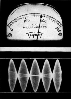
Fig. 1. The "two-tone" linearity test signal which was used to adjust the amplifier for low distortion over all parts of the waveshape. At this time, notice only one thing: the top of the pattern remains "unflattened" or "unsquashed." It extends exactly from one horizontal line on the oscillogram to the other. These lines represent the point of peak linearity capability of the amplifier. No splatter caused by "limiting" of peaks can occur as long as we do not try to drive any type of signal past the amplitude point represented by the lines. This holds true in all of the pictures.
Fig. 2 shows the amplifier being driven into distortion on the two-tone signal. The peak linearity capability has been exceeded. Note the flattening of the peaks. Now notice the meter reading as compared to Fig. 1. The meter shows what we all like to see - more power - but the 'scope indicates that it is distorted power.
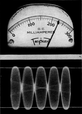
Fig. 2. The amplifier driven into heavy distortion on the same test signal. The linearity capability has been exceeded. Note the "squashing" of peaks. Now compare the meter reading to that of Fig. 1. The meter shows what we all like to see - more power input; but the 'scope indicates this is distorted power.
Fig. 3 shows the result of introducing a single audio tone into the speech amplifier. It may not look like sine-wave audio, but this is because we no longer have an audio signal. The s.s.b. exciter converted the single tone audio into single frequency r.f. - practically the same as an unmodulated carrier. Look at the plate meter! On steady signal the amplifier has no time to rest. It works regularly - not in spurts as on voice. The meter has a chance to indicate full maximum signal input.
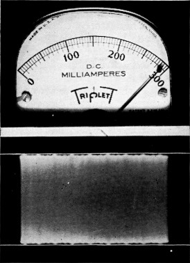
Fig. 3. The result of inserting a steady audio tone into a s.s.b. exciter. It may not look like sine-wave radio, but that is because we no longer have an audio signal. The exciter converted the single tone audio into single frequency r.f., the same as an unmodulated carrier. (The slight ripple represents imperfect sideband and carrier suppression and harmonic audio distortion.) Look at the meter! On steady signal the amplifier has no time to rest. It works regularly - not in spurts - as on voice. The meter has a chance to indicate maximum signal input.
Fig. 4 shows an actual voice waveshape. The sound used was a sustained "O-o-o-h-h-h." Notice that the "peaks" just reach the limit lines. Look at the meter. Oh, how sad! That's the current we must use to calculate power input!
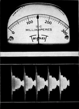
Fig. 4. Actual voice waveshapes. A sustained note was used for clarity of presentation. Notice that the high-amplitude low-energy peaks which are encountered in the voice just reach the lines representing maximum permissible amplitude. Look at the meter. Oh, how sad! That is the current we must use to figure power input.
Fig. 5 is the condition where the audio "gain" is increased to correct the low meter reading. Yes, the meter reads more, but take a look at the 'scope. Those peaks are really flattening. Splatter! Zounds! No escape! A clean signal means lower meter reading, while greater deflection causes trouble.
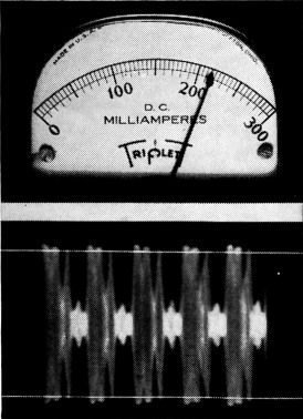
Fig. 5. The audio gain increased to give a more satisfying meter reading. Yes, the meter reads more, but look at the scope. Those peaks are really flattening. Splatter! Zounds! No escape! A clean signal dictates low meter reading, while greater deflection causes trouble.
Fig. 6 shows the same voice sound, purposely altered by audio compression, to increase the "average-to-peak" ratio. Notice that the meter again shows an increase over the conditions of Fig. 4. This is also due to the flattening of the waveshape. Distortion of the audio is present, but no splatter results if the new frequencies are carefully filtered out early in the exciter. New frequencies resulting from r.f. linear amplifier flattening cannot be filtered out. They will be transmitted to plague adjoining channels.
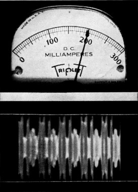
Fig. 6. Another voice sound, purposely altered by audio compression to increase the "average-to-peak" ratio. Notice that the meter again shows an increase over the conditions of Fig. 4. This is also due to "flattening" of the waveshape. Distortion of the audio signal is again present, as it was in Fig. 5, but no splatter is transmitted if the resulting new frequencies are carefully filtered out early in the exciter. New frequencies, caused by r.f. amplifier flattening, cannot be removed. They will be transmitted to plague adjoining channels.
Study of the photographs reveals that there is, as previously mentioned, lack of connection between d.c. meter readings and the type and quality of actual amplifier output.
The situation looks rather gloomy, doesn't it? Is it possible for an average amateur to operate a linear amplifier properly without access to laboratory measuring techniques? Well, the best answer I can give is that hundreds are doing it every day. Perhaps the meters don't give all the necessary indication, but never underestimate the flexibility of an amateur. The trial-and-error system can do wonders.
Splatter
A chain of two or more linear amplifiers, upon construction, is hardly ever able to develop maximum rated output without considerable adjustment. Luckily, s.s.b. transmitting and receiving techniques have the valuable property of making nonlinear amplifier distortion and splatter stick out like a sore thumb. While the same amount of distortion would be partly hidden by the voice sidebands of a double sideband signal and be somewhat obscured by lack of selectivity in an ordinary receiver, such is not the case on s.s.b. There is no such thing as distortion splatter which appears on only one side of the carrier frequency.
A s.s.b. receiver has an opportunity to view, generally unhindered by readable signal from the s.s.b. exciter, the amplitude, nature and frequency spread of nonlinear amplifier splatter appearing on the unwanted sideband. This situation makes possible accurate and worth-while on the air reports of amplifier performance. In cases of "peak limiting" distortion, one can simply turn down the gain until the person at the receiving end reports a clean "unwanted" sideband. Changes can then be made to try and allow more power without degrading the signal.
Power input
Now what about power input? Ask a s.s.b. operator exactly bow much power he is running. The answer might sound something like, "Well, the plate voltage is 2000 and the meter kicks up to about 200 mils on voice peaks. That's about 400 watts. Of course, that's only meter reading. Actually, the peak power is a lot more than that."
Now really pin him down. Ask him what his "peak" power really is. For that matter, what does he mean by "peak power"? Chances are, his eyes might take on a rather furtive look. He might mention something about multiplying the meter reading by the factor 1.57. Don't press him too far. You might become as confused as he is.
Actually, the power-input situation is not nearly as complicated as it is confused. The indiscriminate use of the word "peak" to describe three distinctly different conditions is detrimental to the clarity of the otherwise fairly simple matter of power-input considerations.
The three uses of "peak," as heard on the air and seen in print, are "instantaneous peak power," "peak envelope power," and "meter peak, on voice, power." Unfortunately, it has seemed fashionable to omit the qualifying terms and call any one of them "peak power." When this happens, even a person who understands the situation perfectly must determine which yardstick is being used before giving intelligent consideration to the particular situation involved.
There are two ways which I could use to explain the different kinds of "peak power." One would be to draw a rather involved illustration of a modulated r.f. signal, showing both individual r.f. cycles and cycles of modulating voltage. The other, which I shall try, is to explain the same efects in a non-radio example which closely parallels the case of modulated r.f. energy.
Our example is to be a "four-way" reading lamp, one that plugs into the 110-volt a.c. socket and allows the user to select various conditions of brightness. One setting is "off" - the others range from "dim" to full intensity of the 100-watt bulb. Now let's imagine that this light bulb represents the r.f. output signal of a s.s.b. transmitter, not in the usual sense of a "dummy load," but with the more abstract view that each cycle of 60-cycle a.c. current represents a similar cycle of high-frequency energy in the r.f. signal. Thus the lamp, burning steadily at full brilliance, represents a s.s.b. amplifier with full "inserted carrier" of 100 watts. Now, still in the abstract vein, the brightness control switch of the four-way lamp will be used to represent modulation. The switch is made to vary the brilliance of the lamp at a fairly slow and sporadic rate from one intensity to another. This simulates voice modulation. The remaining item in our flight of fancy is something to represent the plate milliammeter in the transmitter. Let's say that we connect an a.c. ammeter, with a very sluggish movement, in series with the a.c. cord to the lamp. This simulates the inability of a plate meter accurately to follow voice modulation. We are now ready to demonstrate the meaning of "instantaneous peak," "peak envelope or maximum signal," and "meter peak, on voice" power.
To find "instantaneous peak power," we turn our 100-watt light to full brilliance. For simplicity, let's say that the r.m.s. voltage is 100 instead of 110. Ohms Law says that the r.m.s. current is 1 ampere. Consider only one cycle of the 60-cycle wave. The "crest or instantaneous peak" voltage in this cycle is 1.41 times 100 volts. This is 141 volts. The current at "peak" is 1.41 amperes. If P = IE, the concept of "instantaneous peak power" says that 200 watts of power exist for an infinitely small period of time at the crest of the cycle. What does this mean from the point of view of a man reading a book? Nothing! He's got a lamp that gives a hundred watts of illumination and he knows it. The same holds true in a radio transmitter. "Instantaneous peak power" has very little value in everyday operation and adjustment.
Now to the heart of the matter - "peak envelope power" or "maximum signal power." This is possibly the most useful of our terms. It is the way tube manufacturers rate their product. More often than not, it is meant when one sees "peak" mentioned in print. What is the value in the case of our light bulb example? -100 watts: it's as simple as that! Just a minute! How can the 100 watts be "peak power" and still be the value determined by multiplying average r.m.s. voltage times r.m.s. current (100 volts times 1 ampere)? This certainly gives "average" and not "peak" power. In this case, the word "peak" no longer refers to the crest of the 60-cycle wave. To show what is meant, we no longer run the lamp at full power, but simulate modulation by varying the average power all the way from zero to maximum. Now the light bulb (or amplifier) doesn't work fully all the time. It has comparative periods of rest because the signal is pulsating at a sporadic rate. In this case "peak" refers to the fact that the full 100 watts average power only exists for a relatively short period of time. So short, in fact, that the sluggish a.c. meter in the line would never have a chance to indicate an amount of average power approaching the 100 watts we know briefly exists.
The obvious solution to determining " maximum `average' signal power" is to switch the lamp to full brilliance and leave it there while the meters catch up. The same holds true with a s.s.b. transmitter. Never measure "peak envelope or maximum signal power" under voice conditions. Insert carrier or whistle into the microphone and the meters will accurately record this kind of "peak" power. From a strictly r.f. point of view, we are still dealing with " average power " values. These should be familiar to all of us.
"Meter peak, on voice, power" is fairly self-explanatory. I have said that the a.c. meter in our lamp cord was far too sluggish to follow even the relatively slow variations of power which represented modulation. It has already been explained why power figures derived from fluctuating d.c. meters are nearly useless as an indication of amplifier performance unless correlated with other measurements. I mention this type of power again only to show the need for learning what kind of "peak power" is being used whenever the subject arises in a discussion of linear amplifiers.
Perhaps unfortunately, from one point of view, the regulations require that s.s.b. transmitter power be determined from meter swings on voice. This has the effect of keeping the pressure on an amateur to achieve more meter swing. That's fine, if it isn't done at the expense of linearity. This measuring system leads to an interesting situation. If one has an amplifier that "talks up" to a kilowatt, he wouldn't be able to whistle into the microphone without exceeding the legal limit. However, the "maximum signal power" would be the same in both cases.
Earlier I mentioned the figure 1.57 in connection with "peak" power. Never use it unless you are dealing with "two-tone" tests. What is a "two-tone" test? Just because a s.s.b. exciter is generally used as a source of signal for this linearity test doesn't mean that it is a complicated situation. Actually, two ordinary r.f. oscillators, separated in frequency by several hundred cycles and simultaneously feeding equal signals into a linear amplifier chain, would work equally well. I won't go into the reason why two steady frequencies, rather than one, are used to show distortion. However, one thing may seem strange. The average amplifier power, as read by the meter, is much less with two signals than it is with one. Due to the combination of the signals, the amplifier no longer works all the time. It has periods of rest. The "maximum signal power" remains at full value, but the "average-reading" meter indicates far less current. If the amplifier is Class B, the meter now only reads about 64 per cent of its value for one signal of the same maximum amplitude. The reciprocal of .64 is 1.57. Thus the meter reads 1.57 times as much on a single signal (such as carrier) as it does on a "two-tone" test. This factor only applies to Class B operation. Class AB2 and Class AB' have respectively lower ratios of difference in meter readings between signals of one and two frequencies. Continuing in the same direction, Class A entails a ratio of unity because there can be no change of plate current, regardless of the type or number of signals.
From the above, one can see that the figure 1.57 should only be used in one specialized case, never when referring to voice deflection of a meter. A person can't look at a dancing plate meter and accurately see that his "maximum signal or peak envelope power" is a certain given amount. As a final check to prove that the factor 1.57 actually works out in practice, refer back to the photographs and compare the currents in Figs. 1 and 3.
Adjustment without a scope
This isn't basically an article on linear-amplifier adjustment, but I am going to give an example to demonstrate the proper use of d.c. meters when nothing better is available. The procedure falls into the "cheap and dirty, but rather effective" class.
Before I proceed I point out that throughout this article I have mentioned only the "final amplifier." Actually, flattening and distortion may occur in any driver stage. I do not think it necessary, for our purposes, to stress meter readings and waveshapes for other stages. The indications occurring at the output of the final accurately reflect the condition of earlier stages. Of course, in actual practice it is necessary to locate and work on the weak link.
Let's say that I have an amplifier whose specs call for a plate voltage of 1500 and maximum signal current of 300 ma. (Remember, the manufacturer means on a single steady signal, not voice.) First, I insert some carrier from the exciter. I tune the grid and plate circuits to resonance as indicated by an output indicator. (Any type of output indicator connected to the feedline will do.) Next, I adjust the coupling of the feed-line to the final. The coupling is set for maximum power output at a given plate current at resonance. If the coupling is increased, the d.c. plate current goes up, but the output either remains constant or decreases. This point of maximum output for a given amount of input comes close to the magic point of proper adjustment for all linear amplifiers. The old method of loading by reference to "dip at resonance" is not recommended. Once we have reached the suggested adjustment, we have had it as far as coupling goes. If the d.c. current is less than 300 ma. (for the amplifier under discussion), we simply don't have enough linear drive.
Now, regardless of the power I believe my amplifier should handle, I make a crude check to determine at what point it actually flattens. I vary the amount of carrier insertion, watching mainly the output indication, and note the point at which increasing the carrier no longer results in a rapid increase in output. I now observe the plate meter reading, hoping in this case that it is up to 300 ma. I use this figure to multiply by plate voltage. This is roughly my maximum-signal linear power available. Suppose my linear drive available limits my actual plate current to 250 ma. My maximum signal power is then only 375 watts instead of the possible 450.
Next, I remove the carrier. I change to voice. This is the point where experience in using a 'scope counts. I know that my voice, using the average plate meter, will deflect the meter only about half as far, for the same maximum signal power, as the carrier did. Thus, since my steady signal current was 250 ma., I wouldn't expect much over 125 mA on normal talking. The only way to achieve more meter swing under this set of amplifier conditions and not splatter would be to use properly designed and adjusted compression in the exciter's audio.
Reviewing the preceding material, you can determine that my "meter peak, on voice" or legal power, is only 187 watts (125 mA × 1500 volt). My maximum signal or peak envelope power is 375 watt (250 mA × 1500 volt). The instantaneous peak power is about 750 watts. As the saying goes, "You pays your money and takes your choice."
Actually, your voice might be able to swing the meter somewhat more than mine for the same amount of maximum signal power. If I were using a Class AB amplifier I would expect the meter to swing somewhat higher on voice in relation to its reading on steady signal.
Don't think that I am recommending the above procedure as a replacement for legitimate "two tone" adjustment with a scope. Anyone who has worked with linear amplifiers knows that inserting large amounts of steady signal (carrier or single tone is worse; "two tone" less punishing) has the rather disconcerting and costly tendency of making vacuum tubes melt. Discretion is always indictated when making adjustments. However, if cautiously used, the procedure is guaranteed to do one thing - to produce a signal vastly more neighborly than one generated in an all-out attempt to wrap the pointer around the pin.
While I have been writing, I have had a vague feeling of someone looking over my shoulder and wanting to say, "I always knew there was some reason why those `sidebanders' sound so terrible and are so broad. Now I know. They are all 'meter benders'!"
Well, old man, I don't want to start an argument now, but remember the saying about people who live in glass houses. Just because "sidebanders" as a whole are "distortion conscious" it doesn't necessarily mean that they invented the stuff. Sideband enthusiasts with their s.s.b. receiver, transmitters, and voice-control operation, are actually achieving a worth-while increase in voice communication - per kilocycle per watt per hour. This would be impossible if the linear-amplifier situation was really "rotten."
This is not a plea for more than a small percentage of the present operators to become less meter happy. The purpose is to collect a few facts about the use of d.c. meters in voice circuits and to give some pointers concerning power calculations.
Almost everyone who first uses a linear amplifier in s.s.b. service thinks first of the power available. If things progress normally, a change occurs. At some point he starts adjusting for linearity and then accepts the power that results. When that happens, you know that he has graduated into a new and mature attitude toward our old friend Mr. D. C. Plate Milliammeter.
Howard F. Wright, JR., W1PNB.