Improved bleeder circuit
The arrangement shown in Fig. 1 provides a warning before the bleeder resistance burns out, and also a voltmeter for the output of a power supply.
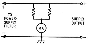
Fig. 1. Schematic of the improved bleeder circuit.
The normal bleeder resistance is made up of two branches in parallel, each branch having twice the resistance of the normal bleeder. A milliammeter connected in the common negative leads reads the normal bleeder current. If one branch of the bleeder opens up, the other branch will still discharge the filter condensers, but the meter reading will fall to half its original value, warning the operator that one branch has burned out and should be replaced as soon as possible.
If the branches are made of equal resistance, each branch of the bleeder can have half the power rating of the normal bleeder. If, for example, the normal bleeder resistance is 25,000 ohms, 50 watts, each branch can be 50,000 ohms, 25 watts.
The output voltage of the supply can, of course, be determined easily by multiplying the current indicated by the milliammeter and the bleeder resistance in series with it. When the branches are equal, this resistance will be half the resistance of either branch.
Any milliammeter will read directly in voltage if the bleeder resistance is 10,000 ohms, or 100,000 ohms, the voltage being 10 or 100 times, respectively, the reading in milliamperes. A 25 mA meter, for instance, will read 250 volts full scale with a 10,000 ohm bleeder, or 2500 volts with a 100,000 ohm bleeder.
Rev. Joseph A. Terstegge, W9LQE.
Caution: The bleeder circuit becomes inoperative if the meter opens up! - En.