A low-cost code-practice oscillator
A.C. power with safety features.
Using a TV horizontal-oscillator coil in the oscillator circuit makes it possible to drive a speaker voice coil without a matching transformer. Combined with a "booster" transformer, the result is an inexpensive self-contained code-practice oscillator.
In looking for a good design for a code-practice oscillator, certain requirements were established: The unit must be powered from the a.c. line yet provide complete isolation for safety; there should be no shock hazard in the keying circuit; and in addition, speaker operation was desired without added cost or circuit complication.
Units have been described using a filament transformer for the tube heaters, with the plate voltage obtained from batteries or a rectifier supply. A study of transformers available disclosed a type used in TV boosters having a plate winding of 110 to 150 volts at 15 to 25 mA, in addition to a filament winding, at a cost of only fifteen cents more than a single filament transformer.
A selenium rectifier was first considered for obtaming the necessary d.c. plate voltage, but further study indicated that a dual-triode tube would be more economical in both cost and space, by using one section as a half-wave rectifier and the other as the audio oscillator.
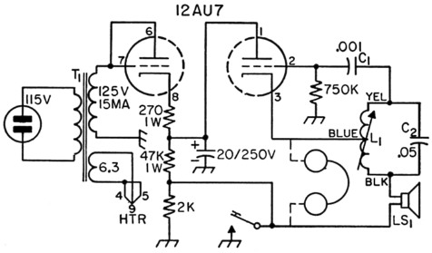
Fig. 1. Circuit diagram of the low-cost code-practice oscillator.
| C1 | Disk ceramic. |
| C2 | Paper. |
| L1 | 100 mH, adjustable (TV horizontal oscillator coil, GE type RLC-091 or equivalent). |
| T1 | Power transformer, 110-150 volts at 15-25 mA; 6.3 V at 0.3 A (Stancor PS8415, Merit P3046, or equivalent). |
| LS1 | 2 inch speaker, 3 to 4 ohm voice coil. |
| Headset may be connected as shown by dotted lines. Resistors are ½ watt unless noted otherwise. Capacitances are in pF. | |
The ordinary audio-oscillator circuit calls for an audio interstage transformer, which accounts for a good portion of the total parts cost. In this design, a horizontal-oscillator coil, as employed in TV receivers, is used in the feed-back circuit. In addition to economy, the adjustable ferrite core provides the means for adjustment of tone without the added cost of the usual potentiometer.
The number of components in the circuit of Fig. 1 is small, as all frills were eliminated in the interests of simplicity and low cost. New parts as checked in a catalog total under $6.00, not including the speaker or cabinet. Many of the parts can be found in special sale catalogs or at bargain counters at most of the larger supply houses. The parts for this particular unit, bargain-purchased, amounted to only $4.03. An additional $1.05 provided a 2 inch speaker.
The circuit
Referring to the circuit, it will be noted one triode section of the 12AU7 functions with grid and plate tied together as a half-wave rectifier. The 270 ohm resistor in the cathode lead limits the peak current, and in conjunction with the 20 µF condenser provides sufficient filtering to give a crystal-like tone. The two resistors in series across the plate supply serve as a bleeder and help to hold the voltage under control when the oscillator section is not operating.
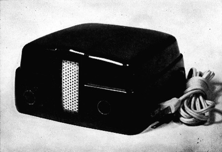
The author's oscillator is built in a plastic cabinet taken from a surplus electric-blanket control. The knob on the left is the a.c. switch; the key plug is inserted through the hole at the right.
The second triode section of the 12AU7 functions as an oscillator in a Hartley circuit in which the plate is at ground potential for audio, with output taken from the cathode circuit. The voltage drop across the 2000-ohm resistor in the plate-supply section provides the necessary 10 volts to bias the triode to cut-off. Only the bias voltage of 10 volts appears across the key.
The 3-4-ohm voice coil of the usual 2- to 4 inch speaker is connected directly in the cathode return, eliminating the output to voice-coil transformer usually required. A speaker without the output transformer compares in cost with low-cost 'phones, therefore speaker output can be obtained without increased cost. If it is desired to use headphones, they may be connected at the points indicated. Suitable output was obtained using 'phones from 500 ohms up. (If the speaker is omitted, the negative supply lead is connected directly to the bottom of L1.)
The heater circuit should not be grounded, because the full plate voltage would appear between the cathode and heater in the rectifier section. With the heater floating, the cathode-to-heater insulation of the two sections is in series, providing sufficient rating for the voltage used.
Construction
To benefit from the circuit design, the unit should be completely enclosed in a cabinet. A midget speaker case makes a fine enclosure, and can be fitted with a subpanel and, if required, a perforated metal back plate. Alternately, a sloping-front meter case can be easily fitted with a grille at even less cost.
The original unit pictured was constructed in a case which may be recognized as a surplus electric-blanket control. A perforated metal speaker grille replaces the original thermometer-type dial arrangement. The knob on the left is the off-on switch which was an original part. The key jack is located behind the hole on the right. Although these surplus units have been available for a nominal price, few parts, other than the case, are adaptable to this construction.
Wiring
Wiring is straightforward and no difficulty will be experienced if the socket terminals are checked carefully and the proper polarity of the 20 µF electrolytic filter condenser is observed. Polarity of the coil L1 is not critical, in event one of another make is used and its leads are coded differently from the one shown (the center-tap must of course be correctly identified). Since the values of L1 and C2 determine the tone, any large deviation in L1 may require a change in the value of C2. A simple trial-and-error process will achieve a pleasing tone.
Robert E. Foltz, W9GBT.