Simple single-band preamplifiers
More gain for the receiver.
The author found that this little fixed-tuned preamplifier helped a lot in pulling in State-side signals on his 75A-1 while he was in the South Pacific. It can be duplicated with a handful of parts and a couple of spare hours.
0ccasionally we all wish we could get a little more gain out of the receiver, particularly one not employing an r.f. stage. A very satisfactory way to improve the gain is to add an r.f. preamplifier ahead of the receiver. The ultimate, of course, would be a bandswitching unit to cover all bands. However, the majority of hams seem to confine their operations to one or two bands, and the cost and complexity of constructing a switchable unit makes it desirable to utilize a simple preamplifier confined to a single band. Fig. 1 illustrates a preamplifier for any one band from 80 to 10 meters. It requires a minimum of parts, expenditure, or labor, and will pay big dividends in bringing in a lot of heretofore unheard signals.
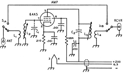
Fig. 1. Circuit of the miniature preamplifier. All 0.001 µF capacitors are disk ceramic. C1 and C2, when used, are 20 pF low temp. mica or ceramic (see table).
Construction
In the model illustrated, a 6AK5 tube was used, but there are several different tubes that could be substituted, such as the 6AG5, 6CB6, 6BC5, 6BH6, or 6AU6. It should be noted that all of the above tubes are not direct replacements for the 6AK5, and a tube manual should be consulted for proper pin connections.
The unit is constructed in a 2¼ × 1½ × 1_3/8 inch Minibox. Provisions are made to switch the preamplifier in or out of the circuit with a d.p.d.t. slide switch. A phono jack is placed at either end of the box for the antenna input, and the output to the receiver. All coils are wound on 3/8 inch Cambridge LS-3 type coil forms which have iron slugs. A small shield may be placed across the tube socket to eliminate any interaction between the grid and plate coils. In the model illustrated the shield has been removed to allow better presentation of the parts lay-out.
A power source of 150 to 200 V d.c. at 10 mA and 6.3 V at 0.3 A is required to operate the unit. This can normally be taken from the receiver, except in cases where the tube filaments are wired in series to operate directly from 115 volts. In the latter case, a small power supply, similar to Fig. 2, may be constructed. If the d.c. voltage is in excess of 200 V, a resistor should be placed in series with the B-plus lead.
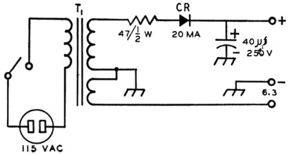
Fig. 2. Circuit of a simple power supply for the miniature preamplifier. T1 is a small TV booster transformer delivering 125 V at 15 mA, and 6.3 V at 0.6 A (Stancor PS8415).
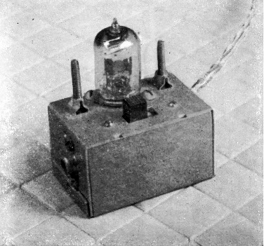
A simple preamplifier built in a small Minibox. The two slug-tuned coils and tube are at the rear, with the slide switch in front.
Alignment
After the unit has been assembled and wired, the coils may first be set to approximate frequency with a grid-dip meter. The tube should be inserted during this check and the slide switch placed in the "in" position.
With the preamplifier connected to the antenna and receiver, apply voltages, place the slide switch to the "out" position, and tune in a signal on the receiver. A grid-dip meter makes a good signal source for this alignment. Place the slide switch to the "in" position and adjust the slugs for maximum reading on the S-meter. If the receiver does not have an S-meter, the preamplifier can be adjusted for maximum signal or noise while listening to the audio output of the receiver with a pair of headphones (this eliminates outside noises). If the receiver has an S-meter, it should show an increase of 4 to 6 S-units when switching the preamplifier in. Coils have not been included for 80 and 40 meters, since most receivers operate satisfactorily at the lower frequencies and a preamplifier is not normally required.
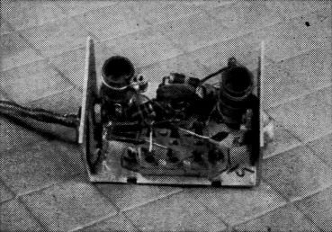
Bottom view of the miniature preamplifier.
| Band | L1 | L2 | L3 | L4 | CA |
|---|---|---|---|---|---|
| 10 | 3 t. | 20 t. | 24 t. | 3 t. | none |
| 15 | 3 t. | 27 t. | 32 t. | 3 t. | none |
| 20 | 4 t. | 27 t. | 32 t. | 4 t. | 20 pF |
All wound with No. 30 enam. on CTC LS 3_1/8 inch iron-slug forms.
W.W. Deane, W6RET.