807s in a 150 watt bandswitching rig
Operating convenience with medium power.
This 150-watt transmitter has a number of attractive features. Provision is made for both crystal and VFO operation. The VFO and multiplier stages are gang-tuned, and a multiband tuner requiring no switching is used in the parallel 807 final. Other features include a metering system, excitation control, and a built-in power supply for the driver stages. The only external unit required is the power supply for the final.
Not long ago, after a shutdown of some 12 years, I moved into quarters that permitted resumption of ham activities. The old 6L6-807 band-switching rig, quite modern when it was built 15 years ago, was dusted off, fired up and put on the air. After replacing a few small parts (casualties of a 5-year storage in sea air), and refreshing my memory on its peculiarities, it gave a good account of itself. However, passage of time showed up two serious drawbacks. The yield of QSOa in proportion to the number of calls using crystal control was very disappointing, and TVI restricted operation to almost impossible hours.
The quickest solution seemed at first to lie in an alteration of the old rig. But the more I thought about adding an external VFO, fitting shielding, installing by-passes, v.h.f. filters and shielded wiring in already restricted space, the more it seemed desirable to rebuild completely so that many ideas accumulated over later years could be included. Consequently, the rig shown in the photographs was born.
The circuit, shown in Fig. 1, is a result of browsing through the ARRL Handbook and issues of QST for the last few years. Either a 6AG7 Clapp VFO covering 1.6 to 2 Mc. (to include the 11-meter band), or an 80-meter Pierce crystal oscillator may be switched (S1A) to feed a 6AG7 buffer doubler followed by a string of 6AQ5 frequency multipliers covering 80 through 10 meters. Each stage (excepting the one covering 14 and 21 Mc.) covers only one band and therefore is more easily stabilized and adjusted for optimum performance than a stage required to cover several bands. S1B and S1C remove screen and plate voltages from the idle oscillator. These voltages are held constant by VR tubes in the low-voltage power supply included in the assembly.
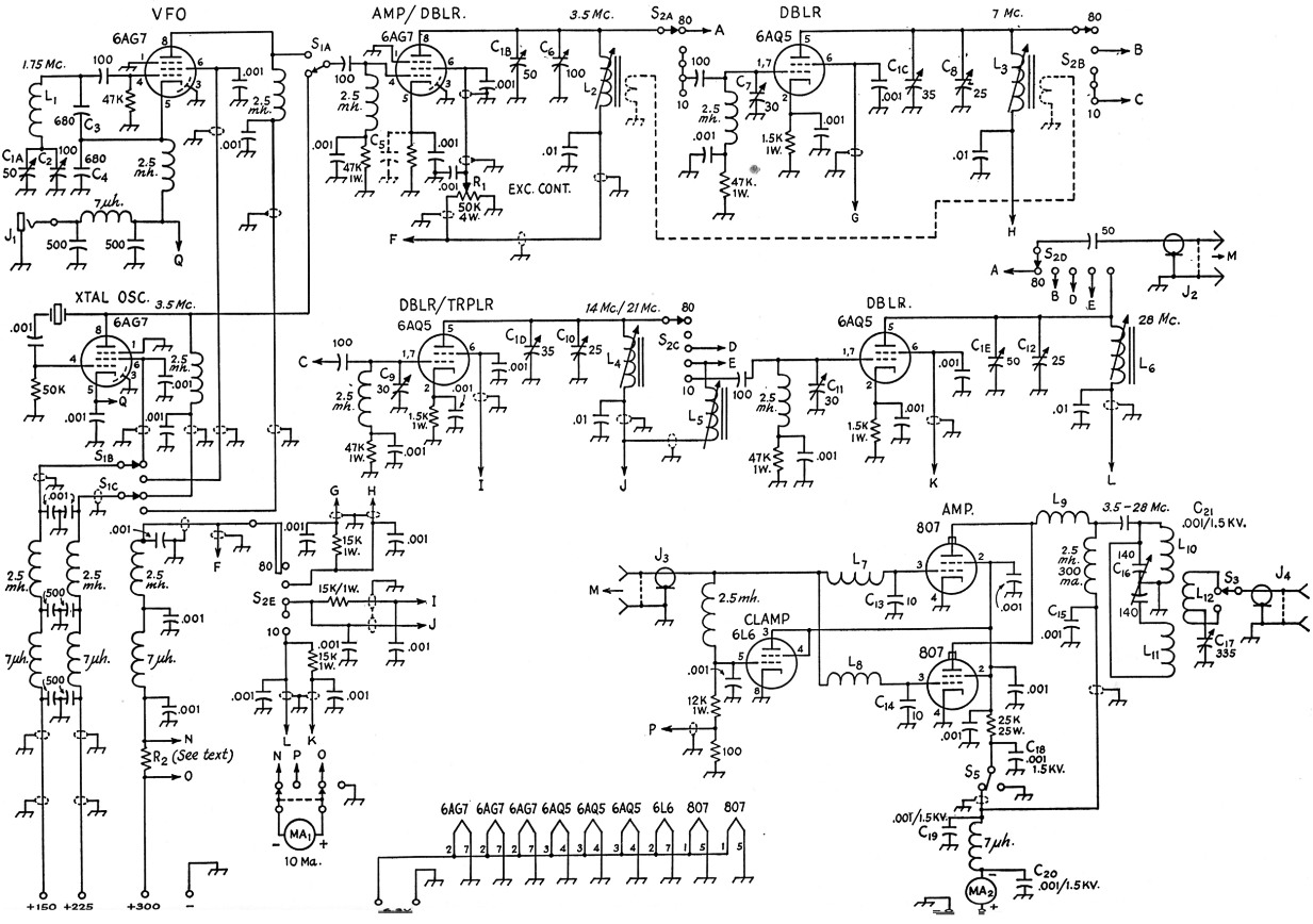
Fig. 1. Schematic of W3WXP's 150-watt bandswitching transmitter. Spanning rechts op MA2 = 600 V.
| C1,C5 | See text. |
| C2,C6,C7,C8,C9,C10,C11,C12 | Midget air trimmers (Johnson type J, Hammarlund type HF, Bud LC-2000 series, etc.) |
| C3,C4,C13,C14 | Silver mica. |
| C15,C18,C19,C20 | 1600 volt disk ceramic (Erie 1R58V, etc.) |
| C16 | Dual variable, plate spacing 0.03 inch minimum (Bud CE-2046). |
| C17 | Midget variable (Bud MC-1860, Hammarlund MC-325-M, Johnson 140R12, etc.). |
| J1 | Open-circuit phone jack. |
| J2,J3 | Shielded phono type jack. |
| J4 | Coaxial connector. |
| S1 | 3 p.d.t. rotary (Centralab 2507, Mallory 174C, etc.). |
| S2 | 5 wafer 5 position ceramic rotary switch (Centralab P-123 index assembly, 4 type X wafers [A, B. C, D]; 1 type P1S wafer [E]). |
| S3,S5 | S.p.s.t. rotary. |
| S4 | D.p.d.t. rotary. |
All other capacitors disk ceramic.
Note: 6AG7 buffer cathode resistor - 1.5K, 1W.
Unless otherwise specified, all resistors ½ watt.
All 7 µH v.h.f. chokes Ohmite Z-50.
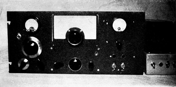
The 150-watt band-switching transmitter and its high-voltage supply. The standard rack panel is 8¼ inches high (see text). Grouped to the left fare MA2, S5 (see text), the National AM dial for C16, and controls for C17 rand S2. Below the National ACN dial for the exciter gang are controls for R1, S2, and S1. To the right are MA1, S4, and the two low-voltage power-supply switches.
The output of any multiplier stage may be switched (S2A - S2D) to feed a final using a pair of 807s in parallel. (6146s could be substituted with a saving in space, although some details might have to be altered.) S2E removes plate and screen voltages from the idle multiplier stages. The multiplier stages are tuned simultaneously with the VFO by ganging their tuning capacitors (C1A - C1E) to the VFO frequency control. Thus, the tuning controls are reduced to three, including the output coupling control.
The 6AG7 amplifier-doubler doubles frequency only when working from the 1.6-2 Mc. VFO Crystals in the 3.5 Mc. region are used in the crystal oscillator, although 160 meter crystals may be used if they are on hand. The 6AQ5 doubler-tripler is shifted from 1.1 to 21 Mc. by switching L5 in parallel with the 14 Mc. inductor, L4, thus reducing the effective inductance for the higher-frequency band.
C2, C6, C8, C10, C12, and the adjustable slugs in the multiplier plate inductors provide convenience in adjusting the tracking of the multiplier circuits. C7, C9 and Cu are included so that the circuit capacitances will remain the same whether a multiplier stage is working into the final amplifier or into the following multiplier stage. This is necessary to preserve tracking.(1) The potentiometer R1 in the screen circuit of the 6AG7 buffer-doubler is used to adjust excitation and is a convenience no rig should be without.
When the rig was first fired up, the 6AG7 buffer-doubler oscillated. This instability was eliminated by connecting a second by-pass, C2i shown in dotted lines, at the cathode, and experimentally grounding it at various points on the chassis until the right spot was found. Slight differences in wiring or layout may make this unnecessary. Another oscillation showed up in the 40-meter 6AQ5 stage. This was cured by a 1-turn neutralizing link, also shown in dotted lines. This link may or may not be required in every case.
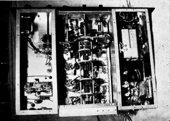
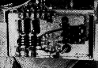
Bottom view showing components underneath the three chassis. In the exciter chassis at the center, the low-frequency circuits are toward the panel and the 10-meter circuit is at the rear of the chassis. Coils and trimmer capacitors are in groups around the associated bandswitch wafer.
To avoid switching in the final amplifier, a multiband tuner(2) is used in the output tank circuit. S8 selects a proper proportion of the output coupling inductor, L12, depending on the output frequency. C17 is the output coupling control. L7, L8, L9, C13 and C14 were installed to suppress parasitic oscillation. The two capacitors are also an aid in reducing TVI. The 807s are protected by a 6L6 screen clamper. S5(3) grounds the screens while tuning up the exciter.
Two milliammeters are included. A 10 mA unit, MA1, may be switched to read either final grid current or total exciter current. The resistor R2 is a 20 times shunt to increase the full-scale reading to 200 mA. The shunt was made from copper wire as described in the measurements chapter of the ARRL Handbook. The second meter, a 300 mA unit, reads combined plate and screen currents to the 807s.
All power leads are of shielded wire, and have filters for the operating frequency ae well as for v.h.f. The low-frequency filtering may not be strictly necessary, but it does help to keep fundamental r.f. out of the power supply and off the a.c. line where rectification might take place, resulting in the generation of TVI.
Construction
A system of permanent yet flexible construction was found in building the exciter, final amplifier and low-voltage power supply as separate units. Any of these may be quickly removed from the assembly for replacement, rebuilding or use elsewhere. A pair of 5 × 13 × 3 inch chassis takes care of the low-voltage power supply and the final amplifier. The exciter is assembled in a 12 × 7 × 4 inch ICA "Flexi-mount" box.
In the exciter unit, the VFO occupies the front end, with the tuning capacitor C1A enclosed in an aluminum box on top, and the inductor L1 mounted underneath on a small stand-off insulator fastened against the front wall. In the rear/top view, the crystal and crystal-oscillator tube are to the right of the tuning-capacitor box, and the VFO tube is to the left, followed by the string of multiplier tubes. The 10-meter stage is at the rear of the chassis.
Underneath, the four remaining units of the tuning gang, C1B-C1C, are lined up at the center of the chassis. They are driven by a brass gear attached to the tail shaft of the VFO tuning capacitor, C1A above, and another gear on the shaft of the first multiplier tuning capacitor, C1A, below. The gears engage through a slot cut in the chassis. (I may say that this arrangement is not as satisfactory as it might be and if I were going to do the job again, I would mount the entire gang on top of the chassis, cover it with a long narrow box of aluminum, and feed the stator leads through holes to the switch sections below.)
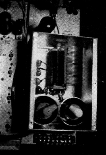
Looking down into the final-amplifier box. The amplifier tubes are submounted. Also shown is the 6L6 clamper tube.
The bandswitch, with the wafers spaced approximately according to the tube spacing, is mounted between a partition that shields the VFO from the rest of the exciter, and the rear wall of the box. The last wafer, S2E, is mounted on the outside of the box. The partition shielding the VFO also serves as a mounting for the crystal-VFO switch, 1S1, and the excitation control, R1.
In the bottom view, the inductors for the multiplier stages and the padder capacitors, C6, C8, C10 and C12, are to the right of the band-switch. The tube sockets and the grid trimmer capacitors, C7, C9, and C11, are to the left. The VFO trimmer, C2, is to the right, close to the front wall of the chassis. (Its control shaft is behind the crystal-oscillator tube in the rear view.)
A 1 inch extension of aluminum is attached to the rear of the exciter box to make its over-all length 13 inches to match the adjacent chassis. The r.f. filter components and the 6AQ5 screen resistors (as well as the last section of the band-switch, 82E), are placed inside the enclosure, and the compartment is fitted with a cover plate of aluminum. A terminal strip is set in the upper edge.
Capacitor Gang
In building this unit, I made use of components on hand whenever possible. The condenser gang, C1, is made up of individual capacitors connected together with shaft couplers. Care must be used in selecting capacitors that will fit into the length of the "Flexi-mount" box. One inch must be allowed for the hub of the National ACN dial, leaving only 11 inches for the tuning gang. A suitable gang can be made up of Bud "Tiny-Mite" dual capacitors. A dual 25 pF unit (LC-1661) with its sections connected in parallel will serve for C1A. A dual 50 pF unit (LC-1662) can be used for C1Bs and C1C. Five plates (3 rotor and 2 stator) should be removed from the C1C section. Another dual 50 pF unit can be used for C1D and C1E, removing plates, as above, for C1D.
Amplifier
The amplifier is enclosed in a homemade aluminum box fastened to the top of the 5 × 13 × 3 inch chassis. The box is 4½ inches high (limited by the height of the 8¾ inch panel), the same width as the chassis, and long enough to include the 807s and the multi-band tankcircuit components, yet leave sufficient room for the 6L6 clamper tube in front and a terminal strip at the rear. The sides and top are perforated to provide ventilation. The tuning capacitor C14 and the output inductors L10, L11 and L12, are placed centrally in the box, and as far toward the front as possible. The capacitor is mounted directly on the front wall of the box, and rests against the chassis. In an effort to reduce the length of the path between the rotor of the capacitor and the 807 cathodes, short leads from each end of the rotor were brought through holes and fastened to the under side of the chassis. To allow room for the 300 mA meter, which has a 2½ inch diameter flange, the dial must be set so low on an 8¾ inch panel that it is necessary to use a flexible shaft between the dial and the tuning-capacitor shaft. With a 10¾ inch panel this would not be a problem, of course.
| L1 | 30 turns No. 30, close-wound.1 |
| L2 | 35 turns No. 26, close-wound.2 |
| L3 | 18 turns No. 26, 5/8 inch long.2 |
| L4 | 8 turns No. 26, ½ inch long.2 |
| L5 | 5 turns No. 26, ½ inch long.2 |
| L6 | 3 turns No. 26, ¼ inch long.2 |
| L7,L8 | 1µH (National R-33). See text. |
| L9 | 5 turns No. 14, ¼ inch diam., 3/8 inch long. |
| L10 | 12 turns No. 16, 2 inch diam., 15 inches long (B dc W 3907 strip inductor). |
| L11 | 6 turns No. 14, 1¾ inch diam., ¾ inch long (see text). |
| L12 | 8 turns No. 16, 2 inch diam., ¾ inch long (B dc W 3908 strip inductor). |
| 1 Wound on Millen or National 1-inch diam. phenolic form. 2 Wound on National XR-50 iron-slug form, ½ inch diameter. | |
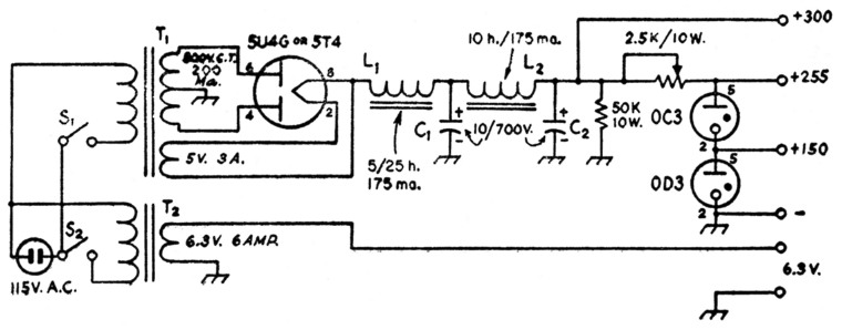
Fig. 2. Circuit of the low-voltage power supply.
| C1,C2 | Mallory TC-92, C-D BRHV-710, Aerovox PRS, etc. |
| L1 | UTC S-30. |
| L2 | UTC S-29. |
| S1,S2 | Toggle. |
| T1 | UTC R-109. |
| T2 | UTC FT-8. |
Holes to clear the bases of the 807s are cut in the top of the chassis, and the sockets are sub-mounted, on a U-shaped strip of aluminum, to a depth that brings the caps of the 807s clear of the top cover of the box. Here again, a 10%-inch panel might provide greater freedom in the method of mounting. Millen shield cans are used with the tubes.
Inductors
The inductors were originally all made from B & W 3907 strip inductor stock as shown in the top view, simply opening up the winding where necessary to provide the proper terminals. However, the high-frequency section, L11, ran warm enough to soften the plastic supporting strips. This difficulty was solved later by making L11 a separate section, wound on a ceramic form. Similar forms may be hard to come by, but it should not be too difficult to make a self-supporting coil of the same inductance, since the dimensions are small. The output coupling inductor, L12, should be placed between Lle and L11.
The output-link switch, S3, and the link tuning capacitor, C17, are mounted under the chassis, as shown in the bottom-view photograph.
Shielded phonograph jacks are mounted near the rear ends of the exciter and amplifier chassis and are connected with a short length of RG59/U coax fitted with phonograph plugs.
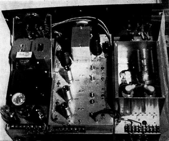
Rear view of the 150-watt transmitter, showing arrangement of components on top of the power-supply and exciter chassis (see text).
Power Supply
The low-voltage power supply is built on the second 5 × 13 × 3 inch chassis. The circuit is shown in Fig. 2. The arrangement of components is not critical so long as they are accommodated in the available space. This section includes the 10-ma. meter and its switch, indicator lights for filament and plate voltage, and a pair of toggle switches to control these supplies. The high-voltage supply is conventional, using choke input and a transformer rated at 600 or 750 V d.c., 200 to 300 mA.Adjustment
After checking the crystal oscillator to make sure that it is functioning properly, the VFO should be checked and its tuning range adjusted to cover the desired range of frequencies. Setting C1 to minimum capacitance, C2 should be adjusted until the oscillator is heard at 4000 kc., or a few kc. higher. Then, with the bandswitch in the 80-meter position, and the milliammeter reading grid current to the 807s, C6 should be set at midscale (C1 still at minimum capacitance) and the slug in L2 adjusted for maximum 807 grid current. Then C1 should be adjusted until the oscillator signal is heard at 3200 kc., and C6 readjusted for maximum grid current. If this last adjustment requires an increase in the capacitance of C6, the tuning range of the 80 meter stage is too small. C6 should then be set at less capacitance than originally, the VFO reset to 4000 kc., and the slug in L2 readjusted for maximum grid current. If the readjustment for maximum grid current at 3200 kc. has required a decrease in the capacitance of C6, the tuning range of the 80-meter stage is too great. In this case, Co; should be set initially at a higher capacitance at 9000 kc.
When an adjustment has been secured where the grid current remains essentially constant across the 80-meter band, the bandswitch should be turned to the 40-meter position. The VFO should be set to the low-frequency end of the band, and a high-resistance voltmeter connected across the 40-meter doubler grid leak. C7 should then be adjusted for maximum voltage. This voltage should remain essentially constant over the band.
The v.h.f. filter components are enclosed in an extension added at the rear of the exciter chassis. The switch section is S2E.
The 40-meter stage, as well as the following multiplier stages, are lined up by the same method used for the 80-meter stage. The band-set condenser is set at midrange in each case, the VFO is tuned to the high-frequency end of the band, the slug in the plate inductor is adjusted for maximum 807 grid current, and then a check made at the low-frequency end of the band, repeating the process if there is a conspicuous difference in grid current at the ends of the bands. On 21 Mc., it should be necessary to adjust only the slug of L5 after the circuit has been lined up on 14 Mc.
If parasitic oscillation occurs in the final amplifier when plate and screen voltages are applied, L7, L8, and L9 should be adjusted, a turn at a time, until the parasitic is suppressed. In the multiband tuner, it is advisable to adjust L11 carefully so that 14 Mc. comes at maximum capacitance of C15, and adjust L10 so that 7.3 Mc. comes with the capacitor near minimum capacitance. This procedure should result in maximum separation between fundamental and harmonic resonances.
After the steps described earlier were taken, no sign of instability could be found on any band with the rig running wide open, regardless of the setting of the tuning or excitation controls. After a high-pass filter had been installed at the input of the TV receiver to prevent overloading, no TVI could be detected on a receiver running in the same room, with a separation between antennas of only 10 feet. The rig can be flipped from band to band with no fussy adjustments and with complete freedom from "bugs" of any kind. Reports on the quality of signal have been universally excellent.
Notes
- At 10 meters, the reactance of the parasitic chokes used (1 µH) becomes appreciable relative to the reactance of C13 and C14 plus the tube input capacitance. This tends to increase considerably the apparent capacitance across the circuit, and this is probably the reason that the 50 pF variable capacitor was found necessary to cover the 10 meter band. It should be possible to eliminate v.h.f. parasitic oscillation without the use of the grid chokes (see recent editions of The Radio Amateur's Handbook). With the chokes removed, capacitor values the same as those used in the 40 and 20 meter stages should be adequate with an appropriate increase in tank inductance. - Ed.
- See QST, July, 1954.
- It is advisable to use a rotary switch at this point, since the switch must stand the full 807 plate voltage. - Ed.
George G. Symes, Jr, W3WXP/0.