Ripple on the S.S.B. scope pattern
Is well known that a perfect single-tone single-1 sideband signal consists of but a single radio frequency. When such a signal is displayed on the face of a scope being swept horizontally at an audio-frequency rate, the pattern is a horizontal band having perfectly smooth and straight upper and lower edges. It is identical with the pattern of any unmodulated carrier.
If the suppression of the other sideband or the carrier is not complete, the edges of the pattern show a ripple. Assuming that the carrier is completely suppressed, the relationship between the desired and undesired side frequencies can be represented by the phasor(1) diagram shown in Fig. 1. AB represents the amplitude of the desired side frequency and BC the amplitude of the undesired side frequency. The latter rotates with respect to AB, with C describing the dashed circle. The rate of rotation is equal to twice the audio modulation frequency since the two frequencies are separated in the spectrum by that number of cycles. At some instant during each such period of rotation point C will reach X and the total instantaneous amplitude will be the distance AX. A half-period later C will coincide with Y and the total instantaneous amplitude will be AY. As displayed on the face of the scope, this time variation is transformed into a ripple along the horizontal edges of the pattern, the maximum vertical excursions lying between AY and AX.
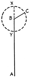
Fig. 1. The mechanism by which the undesired side frequency makes a "ripple" on the desired side frequency of an s.s.b. signal. Other possible spurious components are neglected in this drawing, but can be included if their relative amplitudes, phases, and frequency separation from the desired side frequency are known.
Since the relative amplitudes of the desired and undesired are AB and BC, respectively, the ratio of desired to undesired is AB/BC. This amplitude ratio is also equal to twice the length AB divided by the distance XY. In terms of the scope pattern, this means that the average height of the pattern divided by the vertical distance between a peak and valley of the ripple gives the ratio by which the undesired side frequency is suppressed.
Fig. 2 shows these quantities as they appear on the tube face, together with typical patterns for various ratios of spurious suppression. The latter are drawn as closely to scale as possible, and therefore can serve as a guide to estimating spurious suppression without actual measurement and calculation.
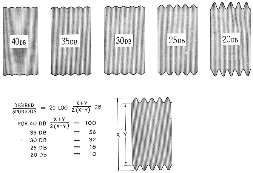
Fig. 2. Examples of scope patterns for various desired/ undesired ratios, and the method of calculating suppression of composite spurious from measurement of the scope pattern.
In examining such a pattern, it is necessary that the horizontal sweep in the scope be synchronized at some submultiple of the modulation frequency in order to get a stationary picture. Without such synchronization the ripple becomes merely a blur. Since the edge of the blur is a straight line, the unwary operator can lead himself to believe he has a "perfect" s.s.b. transmitter when in actuality it may be pretty poor.
It is also necessary, although it should not be, to emphasize that the audio gain must be kept below the point where any stage in the transmitter tends to saturate. Saturation of an amplifier gives a beautiful pattern, but unfortunately, the actual output contains all sorts of spurious that the scope can't show.
Total spurious
The actual situation in a practical transmitter is not quite so simple as it has been outlined above. The assumption that the transmitter output consists only of the desired side frequency and its undesired "image" can seldom be justified in practice. There are always other components present in the transmitted signal even when the audio input is ostensibly a single tone. These are (1) the residual carrier, if it is not balanced out to considerably better than 40 dB below the desired side frequency; (2) components resulting from harmonic distortion either in the audio input signal or added to the signal in the speech amplifier and modulator; (3) intermodulation components generated in r.f. stages.
These components have a definite frequency spacing in the spectrum, always appearing at some multiple of the audio modulation frequency on one side or the other - or on both sides - of the carrier frequency. The amplitudes of the last two, at least, can easily exceed the amplitude of the undesired side frequency in a well-designed single-sideband transmitter. What the scope shows, consequently, is the composite of all the spurious components present.
As a result, the actual shape of the ripple along the edge of the pattern is seldom as conventionally sinusoidal as the ripple in the drawings of Fig. 2. The ripple peaks are a measure of the total effect in about the same way that the corresponding peak-to-peak variations are a measure of the total effect of an ordinary a.m. signal displayed on a scope. That is, when the a.m. signal is tuned in in the normal way, with the beat oscillator off, using a receiving bandwidth large enough to accept the entire transmitted spectrum, the audio output is the total effect of the variations seen in the scope pattern. If the s.a.b. signal is tuned in similarly (using the desired side frequency as the carrier) the audio output from the signal is the total effect of the ripple.
No one component of the several always present in an actual signal can be separated readily from the others in the scope pattern. To do this requires a "spectrum analyzer" such as a receiver having sufficient selectivity for the purpose. Also, the peak-to-peak ripple as shown by the scope is usually leas than the arithmetic sum of the individual components that make up the composite signal because of the non-uniform phase relationship between components. However, it is not likely that any single component would have an amplitude greater than that of the composite ripple. Hence the latter would appear to offer a reasonable basis for rating the desired/spurious ratio of the transmitter. As compared with other methods of rating that might be chosen, it has the advantage of being readily measured with the conventional scope set-up.
A desired/spurious ratio not exceeding 30 dB at any audio frequency within the nominal a.f. band of the transmitter can be achieved if the transmitter is adjusted and operated with reasonable intelligence. On a pattern having an average height of 2 inches (typical of a 5-inch scope) the peak-to-peak ripple height is h6 inch for a 30 dB ratio.
Notes
- The term "phasor" is not used in an attempt to confuse the reader, but to conform with a recommendation of I.R.E. "Phasor" is preferred to "vector" because while the vector representation is convenient for showing relative phase and amplitude of a.c. currents and/or voltages, these quantities are not actually vectors - that is, there is no spatial direction associated with them.