The "extended lazy H" antenna
Rotary beams were unknown in the early days of amateur radio, and most hams contented themselves with horizontal or vertical wires from which, after much patient work, they obtained varying degrees of effectiveness. With the development of the Yagi antenna the 2-, 3- and 4-element rotary beam became commonplace, and it would appear that the trend in this direction is increasing, particularly with amateurs residing in thickly-populated areas where land space is limited. No comment will be included about V beams and rhombics, since this article is written for the amateur who, although he is interested in operating bn several bands, is not prepared to erect a costly mast structure to support several beams and also does not have the relatively-unlimited space necessary for the usual "dream" antenna farm.
The antenna to be described is completely original and to the writer's knowledge has not been described in any local or overseas journal. We have "ZL Specials" and "8P0 antennas" and, for want of a name, thiqantenna might be called the "extended lazy H." Several years ago a conventional lazy H antenna was cut for 14 Mc. and installed at VK2SA. This aerial consisted of two horizontal collinear elements stacked and separated a half wavelength. The top of the array was supported by two 41-foot masts, thus leaving the bottom section only 9 feet above the ground. The effective height of this type of antenna is measured from the halfway point between top and bottom elements and thus, in this case, the effective height was about 25 feet. The observed effectiveness was only about equal to a full-wave Zepp 41 feet high.
Attention was then directed to the possibilities of the "extended double Zepp" described in QST for June, 1938. The height of one mast was increased to 45 feet, to compensate for ground slope, and the antenna was cut for 14 Mc. and erected for NE-SW directivity. Improved effectiveness by comparison with the full-wave antenna was apparent on 14 Mc. W contacts. In addition, some excellent phone contacts were made on 7 Mc. with W stations. Results on 21 Mc. indicated a number of major lobes that gave good DX contacts. From the results it would appear that this type of antenna possesses the desirable feature of good effectiveness on several amateur bands. The gain of the extended double Zepp is given in most textbooks as 3 dB.
The theoretical gain of the conventional lazy H antenna is given as close to 6 db., but it was considered attainable only if it could be supported about 70 feet in the air, so that the bottom elements were at least a half wavelength above ground. This was impossible with the existing masts. Consideration was then given to the possibility of adding two additional extended halfwave lower elements to the extended double Zepp. The additional elements were connected 21 feet down on the feed line,(1) as shown in Fig. 1, and the feed line was transposed to give the proper phasing.
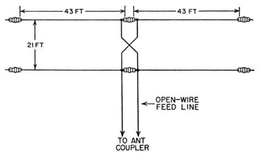
Fig. 1. Dimensions of the "VK Special" 7, 14 and 21 Mc. beam antenna of VK2SA. Whether the antenna coupler will be series- or parallel-tuned will depend upon the length of the feed line and the band in use. At VK2SA the upper wire is 40 feet above the ground.
Results with the modified antenna were very gratifying, as was the ability to operate readily on three bands with the one antenna system. Although the directional characteristics on 21 Mc. are not yet known completely, the signal reports indicate the presence of major lobes giving good general coverage. On 7, 14 and 21 Mc. an antenna tuner is used, and an open-wire line with 4-inch spacing is used between tuner and antenna.
On 14 Mc. the antenna has outperformed all previous wire antennas tried out for W contacts on both long and short paths. The lower two elements were added to the extended double Zepp on December 19, 1954, and numerous W 'phone contacts have been made since that date. The majority of the signal reports are S8 and S9, and nothing below S6 from East Africa. The power input to the transmitter is 75 watt.
An analysis of all signal reports indicates equal if not better performance compared with rotary beams, and it would appear that the gain exceeds 6 dB. Comparison reports have also been made by the simple expedient of removing the two lower elements - the antenna then becomes an extended double Zepp - and the signal was reported to drop 2 and sometimes 3 S points.
Notes
- The point 21 feet down the feed line is a voltage loop, and one would normally connect half-wavelength elements at this point for in-phase drive of all elements. The modification by VK2SA is not the simplest array to analyze, but in view of his excellent results it is thought to be of considerable interest. -Ed.
Walter E. Salmon, VK2SA.