A de luxe amateur-band receiver
Double conversion and mechanical filters.
Here is a home-built receiver with most of the desirable features of a factory-built job and several of its own that can't be found in the manufactured products. If you have ever had the itch to put together your own receiver and experience the pleasure and pride that go with it, don't pass up this article.
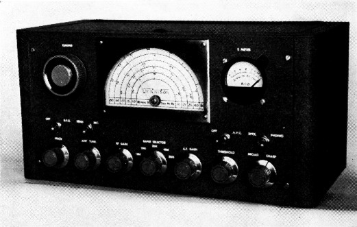
This clean-looking homemade receiver includes such features as double conversion, bandswitching, and two choices of selectivity. The tuning knob is at the upper left - the bottom controls, deft to right, are pitch, antenna tune, r.f. gain, band selector, a.f. gain, noise limiter threshold, and selectivity. The toggle switches, l. to r., are b.f.o., send-receive, a.v.c. and speaker-phones.
The principal features of this receiver are double conversion to eliminate r.f. images, switchable mechanical filters for choice of phone or c.w. reception with extreme skirt selectivity, and bandswitching to eliminate the nuisance of plug-in coils. It is strictly a ham-band receiver covering the amateur bands 80 through 10 meters.
A large illuminated dial, centered on the panel for best appearance, provides direct reading for each band. The tuning drive system is an economical string-and-drum arrangement affording smooth operation. A flywheel on the knob shaft permits rapid excursions up and down the band. Further alleviation of tuning fatigue is secured by means of a large tuning knob; its size nearly equals that of the S-meter and thus helps to balance the panel layout.
Other features include delayed a.v.c., a series-valve noise limiter with threshold control, speaker-phones switch, an antenna trimmer, and a send-receive switch that disables the r.f. stage.
The front end
As shown in Fig. 1, the r.f. stage uses a 6CB6 with both the grid and plate circuits tuned. Reduced a.v.c. voltage is applied to this stage to prevent cross-modulation which might otherwise occur on strong signals with the sharp-cut-off 6CB6 tube.(1) The cathode of the 6CB6 is not connected to the manual r.f. (i.f.) gain control, and thus the r.f. stage runs wide open when the a.v.c. is off. This results in maximum signal-to-noise ratio when hunting for weak DX signals. On the 80-meter band, the gain is held to a manageable level by increasing the cathode bias resistance.
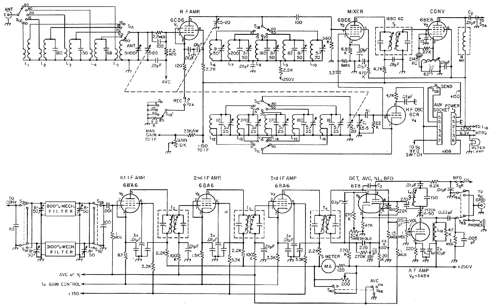
Fig. 1. Schematic of the double-conversion receiver.
All resistors ½ watt unless specified otherwise
All capacitor values in pF unless so specified.
| C1 | 5 pF midget variable (Johnson 5M11). |
| T1 | 1690 kc. i.f. transformer (modified 455 kc. transformer; see text). |
| T2,T3 | 455 kc. i.f. transformer (Miller 12 C1). |
| T4 | 455 kc. i.f. transformer (Miller 12 C2). |
| ANT | 100 pF midget variable (ffammarlund 11F-100). |
| TUNE | 3 gang 20 pF variable (Miller 1461, modified; see text). |
| 8-50 pF trimmers are Centralab 827-D. | |
| 5-25 pF trimmers are Erie 557. |
The send-receive switch, S2, is in the cathode of the r.f. stage. This allows using the receiver to monitor the transmitter. The second section of 82 is connected to the auxiliary socket and may be used to turn on the transmitter simultaneously with the reduction in receiver gain.
The mixer stage and the h.f. oscillator are conventional and require little comment. Auto- matic volume control is not applied to the mixer as it might "pull" the oscillator. The familiar Hartley oscillator circuit is used because it simplifies the coil design and adjustment problems. Plate voltage on the oscillator is low and regulated to secure best stability and freedom from drift. The oscillator fixed capacitors are silver micas and the trimmer capacitors are NPO ceramics. The "zero-set," C1, is mounted next to the oscillator tube.
The tuning capacitor is a small three-gang affair designed for application in f.m. receivers. Its compact size and wide plate spacing adapt it well to this job. The particular capacitor used has contoured plates which spread out the high ends of the bands. This is advantageous in tuning s.s.b. on 75. Tuning capacitors with semicircular plates are available in the event that a more nearly linear dial calibration is desired. One rotor plate was removed from each section of the capacitor to obtain the required capacitance range.
The if section
In a double-conversion receiver, it is necessary to choose the intermediate frequencies carefully in order to minimize spurious responses. Of especial importance is the converter oscillator frequency, harmonics of which must not fall in any of the ham bands. The converter oscillator frequency chosen for this receiver is 2145 kc. and is crystal-controlled in the interest of best stability. The tenth harmonic (21,450 kc.) marks the upper edge of the 15 meter band and serves as a check on the receiver calibration. The only spurious response occurring inside a ham band is the image of the fifteenth harmonic which comes in at 28,795 kc. The thirteenth harmonic (27,885 kc.) shows up between the 11 and 10 meter bands. To avoid confusion and to facilitate rapid calibration checking, these spurious responses are marked on the dial with red ink.
The i.f. transformers are the new miniature type, chosen for their small size. Selectivity is not needed; in fact, the response should be broad enough to allow the mechanical filters solely to determine the selectivity of the receiver. Selectivity curves show that this was achieved without requiring damping resistors across the transformers. The 1690 kc. i.f. transformer was made by removing turns from a 455-kc. unit. No change in coil spacing was necessary to maintain critical coupling.
The converter oscillator coil, L11, consists of 66 turns of No. 38 s.s.e. wire tapped at 22 turns. This coil is a single-pi universal winding 1/16 inch thick with three crosses per turn. It is wound on ¼ inch fiber tubing, slug-tuned, and mounted in a 7/8 inch diameter aluminum shield. Inductance can be varied over the range from 74 to 96 µH.
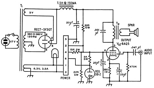
Fig. 2. Schematic of the output amplifier and power supply.
| T1 | Stancor PM8410 or equivalent. |
| T2 | Output transformer; 5000 ohms to voice coil. |
| Power socket is Cinch-Jones S-306-AB | |
Best results with the new low insertion loss (10 db.) mechanical filters requires using shunt feed to keep d.c. out of the windings. A 1600 volt high-voltage coupling capacitor, C2, was used because failure at this point might burn up $70 worth of filters. An alternative solution would be to connect a 15,000 ohm resistor in series with the 8 mH r.f. choke to limit the short-circuit current to a safe value.
Three stages of 1.f. amplification provide more than enough gain to overcome the insertion loss of the filter and to drive the a.v.c. rectifier at an effective level.
The S-meter is a surplus 5 mA tuning meter with a reverse-set pointer. The pilot lamp in these meters is a 3 volt bulb so it is connected across only half of the filament transformer. The plate current of all three i.f. stages passes through the S-meter. Relatively large cathode degeneration in the last two stages helps to linearize the S-meter scale.
The a.v.c. and audio system
The 6T8 tube, V8, is assigned a multiplicity of duties and handles them well. It provides a diode detector, a diode for the delayed a.v.c. system, a third diode with separate cathode for the series-valve noise limiter and, finally, the triode for the beat oscillator.
Coil data for the b.f.o. inductor, L17, are similar to those given previously for the conversion oscillator except that the winding consists of 240 turns tapped at 80. The inductance is adjustable from 600 to 850 µH.
Coupling between the b.f.o. and the detector is obtained through C3 by soldering a wire from Pin 9 of the tube socket to the central shield terminal of the socket. The capacitance between the latter and Pin 1 provides the required injection. The d.c. plate lead from the b.f.o. is brought out to the auxiliary socket so that the b.f.o. can be turned off by means of a switch located on the VFO. This is a convenience when "zeroing" the VFO on a signal. If this feature isn't used, a jumper will be required between Pins 1 and 2 on the auxiliary socket.
The audio amplifier is a 6AB4. The speaker-phones switch, S6, connects the output either to the phone jack or to an RCA phono-type jack. Output from this jack is led through shielded wire to the 6AQ5 power amplifier located on the power-supply chassis.
Chassis layout
The receiver housing is a standard 8 × 16 × 8-inch metal cabinet having a blue-gray wrinkle finish. The 7 × 13 × 3 inch cadmium-plated steel chassis is held to the panel by the bushings of the controls and switches. It was necessary to raise the bottom of the chassis ½ inch above the bottom of the panel to clear the lower front lip of the cabinet. Two lege made of ¼ inch square aluminum rod were attached to the back of the chassis to support it. The central 6¼ inches of the upper lip of the cabinet was filed away Yi inch to clear the rear of the dial assembly.
The central portion of the chassis is reserved for the bandswitching r.f. section. All of the remaining circuits are strung out around the sides and back of the chassis. The mechanical filters are arranged near the front right side to simplify the switching problem. Each filter plugs into two Millen type 33302 crystal sockets and one phone tip jack (see photo of rear side). An aluminum shield measuring 2_1/8 × 2_7/8 inches with ¼ inch lips on all four sides is placed under the chassis midway between the filter input and output sockets. This shield fits snugly against the chassis and its right apron and carries the rear section of the selectivity switch. The front section and the indexing detent are mounted on the front chassis apron. These sections are coupled by a fiber shaft to minimize coupling around the filters. The completed assembly is covered by an L-shaped shield measuring l_5/8 × 3_5/8 × 3 inches.
The output from the 6BE6 converter is led through shielded wire along the front chassis apron to the front section of the filter switch. Four trimmer capacitors are mounted inside the right chassis apron for tuning the filters. Since the tuning is quite broad, it would be possible to omit these and increase the fixed input and output capacitors to 120 pF. A small shield is placed just behind the speaker-phones switch to prevent feed-back into the filter in the event of inadequate i.f. filtering at the detector.
The dial
The dial well is made of 1/8 inch aluminum and measures 4¼ × 6 × 3/8 inches. The lower edge of the well is bolted to the chassis. Placement of the tuning capacitor is such that its shaft projects into the dial well about 3 inch. The end of the shaft is drilled and tapped for a 6-32 screw that holds the lucite dial pointer. A fine line was en graved into the rear side of the pointer and filled with red wax from a crayon. A thin sheet of lucite covers the dial scale to keep it from buckling in humid weather. This and the dial scale are held in place by four 4-40 screws tapped into the dial well. The pilot lamps mount on brackets attached to the rear of the dial well and project through the dial scale and its lucite cover. Holes in the lucite for the capacitor shaft and the dial lamps can be drilled by using a power wood bit with the lucite submerged in a pan of water. A better way is to use a counterbore, drilling quickly halfway through the material from each side.
The two screws passing through the lower edge of the dial scale also support a thin L-shaped strip of metal the width of the dial. This prevents one from seeing down into the bottom of the well and thus improves the appearance of the receiver. This strip and the inside walls of the well are painted black. The screw and washer holding the dial pointer are painted gold.
An opening was cut into the front panel large enough to permit removal of the dial scale for calibration purposes. This hole is covered by a thin piece of window glass held in place by a decorative escutcheon. The escutcheon is made from thin brass with its edges bent down to form a shallow pan just deep enough to cover the glass. A semi-circular window was cut in the escutcheon by drilling a series of small holes and then filing out to final size and shape. The corners of the escutcheon were filled with silver solder and then filed smooth. The completed escutcheon was given a satin chrome finish to get that commercial look. All four corners of the glass window were cut off diagonally to permit passage of escutcheon mounting screws which pass through holes in the panel and rest in tapped holes in the dial well.
The flywheel is a ring of bronze having a cross-section of ½ × 3/8 and an outside diameter of 3 inches. It is bolted to a disk which is swaged to a hub that fits a h-inch shaft. The latter assembly was salvaged from an old TV tuner. After the ring was mounted on the disk, they were turned down to the same diameter in a lathe. The complete flywheel was cadmium plated. The flywheel shaft is a piece of h-inch stainless steel rod which is turned down to inch where the dial cord wraps around it. A bracket made of i4inch sheet iron supports the flywheel and tuning shaft. Bearings were made by sawing regular panel bushings to shorter lengths. The bracket is protected from rust by two coats of gray enamel.
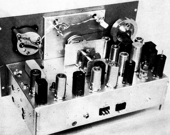
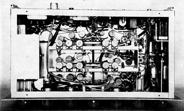
Removing the cabinet shows. the homemade dial and drive mechanism and the general location of the tube and i.f. transformers. The two mechanical filters are located under the S-meter - one has been removed to show how they plug into crystal sockets. The antenna input connector, the headphones jack, the power plug, the auxiliary socket, and the phono jack for audio output to the power amplifier are located on the rear wall of the chassis.
A nylon dial cord rubbed with resin winds twice around the shaft and then passes over the capacitor drum. Inside the drum is a spring to keep the cord taut. Tuning is much smoother and easier than that obtainable with any of the popular constructor's dials now in vogue. There is no danger of getting a glass arm even after several hours of operation.
The r.f. coils
The design of the bandswitching assembly was inspired by a novel and economical arrangement described by WOURQ(2) Reference to this article is recommended for additional pointers on the construction of the assembly.
Computation of the required coil inductances was made using the formula
![]()
where F and ΔF are in Mc. and ΔC is in pF. The term ΔF is the width of the band, F is the mean frequency, and ΔC is the change in tuning capacitance occurring with 85 to 90 per cent rotation of the tuning condenser. The required capacitance and the number of turns on the coils can then be found using either the ARRL type A Lightning Calculator or the Allied Radio coil calculator.
All of the r.f. coils are wound on 2 inch lengths of polystyrene rod. This was purchased in 12 inch lengths and sawed into the shorter lengths. After the ends were trued, one end of each form was drilled and tapped for a 4-40 screw. If these operations are all performed on a lathe, the complete set of coil forms can be made in less than an hour. Next, two No. 60 holes spaced ¾ inch apart were drilled through each form to anchor the ends of the windings. Complete coil data are given in the accompanying table.
| Band | Coil | Tuning range | No. turns | Wire size | Pri. or tap | Coil dia. | Inductance, µH | Fixed cap., pF | Trimmer cap., pF |
|---|---|---|---|---|---|---|---|---|---|
| 80 | Ant., L5 | 3.5 - 1.0 | 77 | 32 | 10 | ½ | 40 | none | |
| Mix., L10 | 3.5 - 1.0 | 77 | 32 | ½ | 40 | none | 5-30 | ||
| Osc., L16 | 5.19 - 5.69 | 44 | 28 | 8 | ½ | 13.2 | 18 | 5-25 | |
| 40 | Ant., L4 | 7.0 - 7.3 | 22 | 22 | 6 | ½ | 3.4 | 68 | |
| Mix., L9 | 7.0 - 7.3 | 22 | 22 | ½ | 3.4 | 82 | 8-50 | ||
| Osc., L15 | 8.60 - 8.99 | 16 | 20 | 5 | ½ | 1.84 | 130 | 5-25 | |
| 20 | Ant., L5 | 14.0 - 14.35 | 8 | 20 | 4 | ½ | 0.519 | 150 | |
| Mix., L8 | 14.0 - 14.35 | 8 | 20 | ½ | 0.519 | 180 | 8-50 | ||
| Osc., L14 | 15.69 - 16.04 | 6 | 20 | 2½ | ½ | 0.37 | 270 | 5-25 | |
| 15 | Ant., L2 | 21.0 - 21.45 | 5 | 20 | 3 | 3/8 | 0.22 | 180 | |
| Mix., L7 | 21.0 - 21.45 | 5 | 20 | 3/8 | 0.22 | 200 | 8-50 | ||
| Osc., L13 | 22.69 - 23.14 | 5 | 20 | 1_3/8 | 3/8 | 0.175 | 240 | 5-25 | |
| 10 | Ant., L1 | 26.9 - 30 | 7 | 20 | 3 | ½ | 0.57 | none | |
| Mix., L6 | 26.9 - 30 | 8 | 20 | ½ | 0.57 | none | 8-50 | ||
| Osc., L12 | 28.59 - 31.69 | 7 | 20 | 2¾ | ½ | 0.4775 | 12 | 5-25 | |
| All coils, except antenna primaries, are ¾ inch long; see text. All wire is plain enamel in sizes shown. All primaries are close-wound near ground end of grid winding, using No. 32 enameled wire. Oscillator fixed capacitors arc silver mica and trimmers are NP0 ceramics. | |||||||||
Bandswitch assembly
The bandswitch, S1, consists of three Centra-lab type R steatite waf-. ers and a P-123 index assembly. The lateral partitions of the r.f. assembly are in the form of shallow pans measuring 7 × 2¾ × ¾ inches. These are held 1¾ inches apart by the side shields. One of these (nearest to mixer tube socket) extends only part way down to the chassis in order to clear wiring entering the mixer chamber. The distance from the front chassis apron to the first partition is 2 inches.
The bandswitch index assembly is fastened to the chassis apron by means of its bushing and nut and the antenna switch wafer is mounted on the index with ½ inch spacers. The mixer (center) and oscillator (rear) wafers are mounted in line on the r.f. partitions by using ½ inch spacers and machine screws. The mixer and oscillator trimmer capacitors are fastened to the upper lips of the partition shields.
A long L-shaped strip of thin copper was placed under the foot of each partition pan so that one extends into the r.f. chamber and the other into the oscillator section. The ground leads from the antenna coils are soldered to the first of these and similarly the ground leads of the oscillator coils solder to the other strip. A ¼ inch wide strip of copper joins the rotor terminals of the oscillator trimmer capacitors. Another strip runs from the center of this strip down to the chassis ground strip. In the mixer chamber, a heavy bus wire supported on stand-off tie points receives the B+ leads from the mixer coils. The mixer trimmer capacitors have their rotors tied together with a ¼ inch copper strap which in turn is strapped to the B+ bus wire.
Alignment and tracking
Before installing the r.f. section, the i.f. and audio were checked and adjusted for proper operation. After the bandswitch assembly was completed, the r.f. coils were inserted and aligned one band at a time. When the receiver was mounted in its cabinet, a final touch-up was made. This required punching a hole in the bottom of the cabinet under each trimmer.
The 20-meter coils are located just to the left of the bandswitch, then come the 40 and 80 meter coils. On the other side of the switch are first the 15 meter and then the 10 meter coils. The order in which the coils were installed is 15, 10, 20, 40, and 80.
To illustrate the method of alignment, the procedure employed for the 20 meter band will be related. First, the tuning capacitor was set near the high-frequency end of the band. A signal generator (grid-dip oscillator) was set to 14.35 Mc. and the 20 meter oscillator trimmer capacitor was adjusted until the signal was heard. The receiver was then turned off and the oscillator tank circuit was checked with the grid-dip oscillator to insure that it was tuned to the high side of the incoming signal; i.e., 16,040 kc. rather than 12,660 kc. Then the receiver was turned on again and the test signal was set to 14.0 Mc. Next, the dial was turned toward the low end of the band to see how much bandspread there was. If there was too much, the turns on the oscillator coil were spread apart a little, whereas too little bandspread meant the turns had to be squeezed together. With the tuning range of the oscillator set, the antenna and mixer circuits were adjusted to track. The test signal was set to 14.35 Mc. and tuned in on the receiver. Then the antenna and mixer circuits were peaked using the S-meter as an indicator. Next, the test signal was set to 14.0 Mc. and tuned in on the receiver. The antenna and mixer circuits were then re-peaked, while noting whether the trimmer capacitance had to be increased or decreased. If it had to be increased, the turns on the r.f. coil in question were squeezed together slightly, whereas if the capacitance had to be reduced the turns were spread apart a little. This process was repeated several times until there was no significant tracking error. After proper bandspread and tracking were achieved, the coil turns were secured in place with judicious touches of polystyrene cement.
The "front end" coils are shielded by the two strips of aluminum at the center of this photograph. Turned-over lips on the shields provide mounting space for the padding capacitors. The shield at the left encloses the output switch section, San, of the mechanical filters. Note the partition at the upper right corner that mounts and shields the b.f.o. pitch control.
Dial calibration
The dial was calibrated by using a 1000 kc. crystal oscillator provided with 100 kc. and 10 kc. multivibrators. A special dial pointer was made, to facilitate accurate positioning of the calibration marks. This consisted of two parallel brass strips soldered to a washer. Just enough space was provided between the strips to permit the passage of the sharpened end of a pencil. When all the bands were calibrated, the scale was removed and permanent marks were drawn with India ink.
Next to an attractive dial, nothing is as effective in achieving commercial appearance as neat labeling of the panel controls. Decals are economical and, if properly applied, look almost as good as silk-screen lettering. The decals used on this job are known as Tekni-Cals. After they have dried twenty-four hours the lacquer film support can be dissolved with acetone. This is done by applying the solvent sparingly with a fine brush. As a result, the painted characters appear as though they were stenciled onto the panel. The shiny reflection from the film support usually observed on most amateur decals is completely eliminated by this treatment.
Performance
When the receiver was completed, it was a pleasurable experience to discover that the amateur bands are not so crowded as old-fashioned receivers lead one to believe. As one tunes across a band, signals suddenly appear and just as rapidly disappear, instead of spreading out and merging together into one continuous bedlam of QRM. The single-signal effect is a phenomenon so startling it must be heard to be appreciated. With the 800 cycle filter in place it is absolutely impossible to hear any trace of signal on the other side of zero beat. And with the 3 kc. filter on phone, one listens to only one sideband at a time, depending on which one has the least interference.
Stability and freedom from drift are excellent. The reserve gain is terrific, the noise limiter works like a charm, and there just aren't any images. Best of all, one doesn't have to mortgage the house to build such a receiver. The mechanical filters can be purchased one at a time as solvency permits, and a wire jumper between the input-and output-filter sockets allows the receiver to be used even before the first filter is obtained. Once you hear what one filter can accomplish, you won't rest until the other is snug in its socket.
Notes
- Pappenfus, "A discussion of receiver performance," QST, January, 1955, p. 24.
- Johnson, "The double-con 6," CQ, January, 1954.
R.C. Dennison, W2HBE.