Tuning the mobile antenna from the driver's seat
A simple remote tuning system.
Various items from military surplus units can be combined to provide a means of easily resonating the mobile whip antenna from the driver's seat.
The writer has expended his share of time and energy in trying out the usual arrangements of mobile installation - transmitter under-dash mounting and trunk mounting, antenna with base loading and center loading, direct coupling and the tapped-coil method (shunt feed), and the usual array of tuning slugs and capacitive hats. The result was considerable frustration and a family gas buggy with enough holes in the body to make a car dealer shudder.
For ease of operation, it was finally decided that the transmitter had no place in the trunk, but belonged up front in constant range of the operator's hand and eye. Furthermore, after shattering an overhead fluorescent lamp in a filling station one night, with a cowl-mounted job, the antenna was transferred to the rear bumper as the only safe place for an 8-ft. whip.
The ability to QSY more than a few kilocycles on any band with such an arrangement was a hopeless dream, nursed in despair for a long time. The usual procedure is to tune up before the car is put in motion, and then stop a couple of times to adjust the antenna to compensate for the change in capacitance as the wind bows the whip backward. When it is desired to QSY, the procedure must be repeated. (This sort of stuff can lead to divorce if the XYL is along expecting an uninterrupted Sunday drive.)
A convenient tuning system
The remote tuner described has solved this problem well, and the author is now at peace with himself and the family. No cross words from the XYL, even after miles of rag-chewing on 75 meters. The antenna is tuned by a variable inductor connected at the base of the antenna, and driven remotely from the driver's seat by means of a flexible shaft. The number of turns needed to cover the 75-meter band is so small that it has little effect on the performance of a center-loaded antenna. Some commercially manufactured tuners, similar in principle, employ reversible d.c. motors for rotating the coil. If a suitable motor and reduction gears are available, fine, but for economy and downright simplicity, the flexible shaft is hard to beat.
To facilitate accurate and easy tuning, a resonance indicator that may be placed within view of the operator is included.
The tuning mechanism consists of the rotocoil and associated rider, springs and a bakelite strip taken from the antenna circuit of a BC-696. Since only about 12 turns are required to cover the band, the coil from a BC-457 may also be used. The BC-696 is often converted for 75 meter components may be simply transferred from the BC-696 to the antenna tuning unit. A coaxial cable is then used between the antenna tuner and the output link of the BC-696.
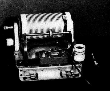
The remote antenna-tuning unit, showing the mounting of the link coupling coil. The thermocouple for the r.f. ammeter and its pick-up transformer are in the foreground.
The BC-442 Command antenna-relay unit (another available surplus item) offers a meter with an external thermocouple that can be used in the remote resonance indicator. If the mounting plate for the BC-442 can also be obtained, it makes an ideal mounting for the tuning unit that can be removed simply by releasing the four slip catches which clamp on the shock mounts.
Construction
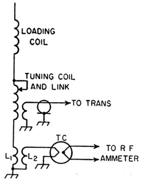
Fig. 1. Schematic of the remote antenna tuning system. TC is an external thermocouple for the r.f. ammeter mounted on the instrument panel. L1 and L2 form the pick-up for the r.f. ammeter.
To begin the construction, completely dismantle the BC-442, and remove the studs to which the cover is fastened, by twisting them out with pliers. The studs on the flanges under the base plate were left intact so that a cover could be mounted over the assembly in case trouble developed from dirt on the rider contact. So far this has not happened. It will be found that when the coil is mounted with one side flush with the edge of the base, and the bakelite mounting strip for the rider and springs is mounted about ¼ inch in from the opposite side, the rider will fit the coil with about the right amount of tension. The rider-spring mounting screws pass nearly through the bakelite strip. The chance of a short can be reduced by mounting the strip over a sheet of mica, fiber or pasteboard cut to size.
It will be observed that the ungrounded, or floating end of the coil has a pressed aluminum mount. This plate is large enough to accommodate a coax receptacle if one of the four corners is sawed off flush with the threads. It was feared that the plate would be twisted or weakened if the receptacle were mounted in the usual manner, so a 7/16 inch hole was drilled for a center, and the fitting mounted flush against this support.
To the coil hub at this end is soldered a short length of brass rod to which the flexible shafting can be connected with a small coupler. This hub looks something like aluminum or pot metal, but it is actually tinned brass and solders very easily if a heavy soldering iron is used.
The pick-up transformer, L1-L2, for the resonance indicator consists of one turn of wire on each coil, wound on a ceramic form around a powdered iron slug. This transformer is mounted at the end of the bakelite strip, near the ground end of the rotocoil, with a machine screw passed up from below the base. The thermocouple can be mounted directly over the rider-spring strip, between the two springs. The mounting screws will have to be slightly longer than the ones that originally mounted the thermocouple. One turn of the transformer is connected between the cold end of the rotocoil and ground. The ol her turn is connected to the thermocouple terminals marked "line." Use a small solder lug on the wire going to the rotocoil.
Matching
In matching the antenna to the line, several methods might be used. The author has tried paralleling two or three lengths of RG-8/U to reduce the line impedance. While a match can be obtained in this manner, difficulty is usually encountered in getting sufficient coupling from the transmitter output to such a low-impedance line, especially with the pi-section output circuits so popular in manufactured mobile rigs. Shunt feed with a separate matching coil at the base of the antenna is feasible, but the most simple and satisfactory arrangement tried consists of a link coil coupled to the ground end of the rotocoil.
In constructing the coupling link coil, it was found that 3 turns of No. 14 could be fashioned so that when one end is grounded, and the other end fastened to a 34-inch stand-off insulator, no other support was necessary. A more rugged and professional-looking job might be done by fastening the turns together at several points with sealing wax or poly spacers. The link is mounted so that it clears the rotocoil by about 1/16 inch, and the turns are spaced about the same distance. The link should overlap about 5 turns at the end of the rotocoil. It will be necessary to remove the solder lug and lead to the thermocouple transformer, and also the end mounting of the rotocoil in order to slip the link coil over the rotocoil. A short length of stranded wire is soldered to the lug on the end of one of the rider springs, and a small banana plug is soldered to the other end to connect to the antenna mount.
Installation
The unit described is small enough that it can be mounted in the trunk, close to the base of the antenna, without interfering with the use for which the compartment was intended. A ground should be made to the car body with a short length of copper braid.
The flexible shaft and tuning head from an SCR-183 were used to drive the coil. This was passed forward under the car and up through a hole under the front seat. The tuning head was mounted on the hump in the center of the floor, as far back against the front seat as possible. This location keeps the control within easy reach, although nothing of the cable is in sight. The hole in the car-body floor is also hidden and is easily covered when the installation is removed. No fastener or adapter could be found for the cable at the tuner end, so it was merely clamped to the car body about a foot from the tuner.
In connecting the line that runs between the thermocouple on the unit and the r.f. ammeter on the dash board, be sure to observe the polarity markings on both the thermocouple and the meter.
Adjustment
Operation of this unit is so simple and straightforward that little explanation is necessary. However, a few pointers may be helpful in getting best results on the first trial. Mount the unit as close as possible to the receptacle at the base of the antenna. Prune the loading coil so that about five turns of the rotocoil are in the circuit at the high-frequency end of the hand. This will mean about seven turns less on the Hi-Q type Master-Mount coil, or slightly more on coils of smaller diameter. Here is where a grid-dip meter comes in handy, although the job is by no means impossible using just the transmitter tuning indicator and the antenna-current indicator. Now try tuning the antenna to the low end of the band by means of the tuner. You will be surprised at how few more turns of coil are necessary. It is advisable to mark each end of the band on the dial of the tuner with paint or white ink. After these adjustments are made, operation consists only of tuning the transmitter and then tuning the antenna for maximum indication of the r.f. ammeter. It may be found that with very low-power transmitters (10 watts or less) there is only a slight indication of current at exact resonance. Meter deflection can be increased by adjusting the leads to the meter transformer so that slightly more than one turn surrounds the core.
As might be expected, the entire system works equally well for receiving. The antenna changeover relay should be placed in or near the transmitter.
Frank T. Morgan, W7RFG.