"Little Oskey" - A monitoring oscillator and keyer
A simple C.W. break-in monitor and code-practice oscillator.
This is a versatile auxiliary unit that will be welcomed to many an amateur shack. Without modifying a receiver or cathode-keyed transmitter in any way, and without the need for extra r.f. pickup, it blanks the receiver and injects a sidetone in the headphones when the key is down. It can also be used as a code-practice oscillator, on those occasions when you can't find anyone to QSO.
Several different methods of c.w. monitoring have been tried at W1CUT. The first, and most simple, involved lowering the gain control of the receiver to a comfortable level while transmitting. However, even with the gain turned down it was difficult to reach a pleasant listening point, and constant adjustment was required. If the station being worked happened to be off the transmitting frequency, it was impossible to monitor without retuning the receiver to the transmitted signal.
The second method for c.w. monitoring made use of a crystal diode to rectify r.f. from the transmitter. The rectified voltage keyed a neon bulb audio oscillator and produced a sidetone. This system proved unsatisfactory because severe TVI was produced by harmonic generation in the crystal diode.(1) Since the r.f. for the unit was obtained from a pick-up wire near the final amplifier there was the danger of high voltage, and when changing bands it was necessary to alter the position of the pick-up wire to obtain sufficient r.f. to operate the unit. Since none of the above monitoring systems proved satisfactory, it was decided to construct a break-in monitor which basically had two jobs to perform. When the key was down the receiver output would be completely squelched and a sidetone would appear in the headphones, and when the key was up receiver output would be fed through to the headphones. Provisions must also be made for:
- No adjustment when changing frequency or bands.
- Installation in station without revision of transmitter or receiver.
- A sidetone that is keyed exactly as tile transmitted signal.
- Keying the transmitter and sidetone simultaneously.
- Mixing the outputs of the receiver and sidetone oscillator.
- Electronic switching from sidetone to receiver output.
- Switching the monitor out for the purpose of zero-beating another signal.
The monitor described here can perform all of the above jobs. Since the unit needs no external excitation, it can also be used as a code-practice oscillator.
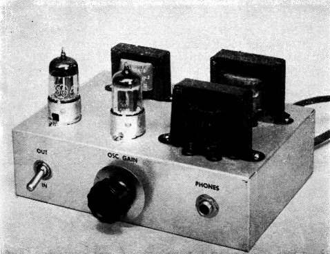
C.w. monitor and code-practice oscillator.
Circuit and construction
No special precautions are necessary in laying out the unit. In fact, the monitor may be built in a cabinet and placed alongside of the receiver. When wiring the unit, it is a good idea to keep the leads carrying a.c. away from the amplifier input to prevent hum. Care should also be taken when soldering the crystal diodes. Holding the diode leads with a pair of long-nose pliers while soldering is good insurance against ruining a crystal. Terminal strips can be used conveniently for mounting parts such as the selenium rectifier and to serve as tie points for resistors, capacitors, etc.
Two small 6 volt filament transformers connected "back to back" are used for obtaining the necessary operating voltages. A novel voltage tripler composed of one-half of the 12AU7 and two crystal diodes supplies the voltages for receiver squelching and the audio oscillator. This voltage is controlled by the transmitting key and is turned on when the key is closed. At this instant (when the key is closed) the sidetone is produced and the receiver is squelched by placing the negative voltage on the grid of the input amplifier tube. When the key is opened the received signal is amplified and heard in the phones, while the sidetone is off.
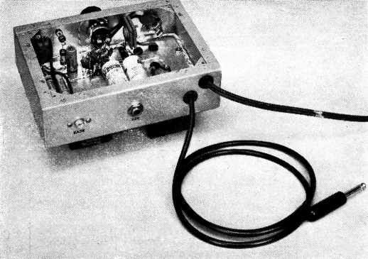
Bottom view showing the connecting cable. The crystal diode voltage tripler can be seen in the upper left corner of the chassis.
The frequency of the sidetone audio oscillator can be adjusted by changing the grid capacitor, C1. If the audio oscillator fails to oscillate, the primary leads of the interstage transformer should be reversed.
High voltage is obtained from the 115 volt side of transformer T1. This is followed by a selenium rectifier and RC filter which provides enough voltage for good amplification in the amplifier-mixer stage.
Operation
It is a very simple matter to insert the monitor into an existing station. The cable from the unit is plugged into the keyed circuit and the receiver output and head-phones are plugged into the unit. Switch S1 is a s.p.s.t. switch on the volume control and is used to turn the unit off and on. If for some reason it is desired to operate temporarily without the unit (such as when zero-beating) the toggle switch, S2, may be opened and the unit becomes inoperative.
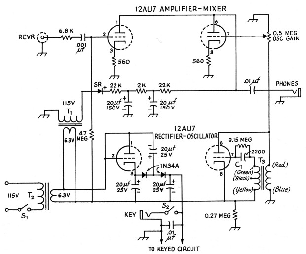
Fig. 1. Schematic diagram of the c.w. monitor.
All resistors watt.
All capacitors in pF unless specified otherwise.
The tube heaters get their power from the 6.3 volt line between T1 and T2.
| SR | Low-current selenium rectifier (Federal 1002). |
| T1,T2 | 6.3 V 1.2 A filament transformer (UTC FT-2). |
| T3 | Interstage audio transformer, secondary-to-primary ratio 2:1 (Thordarson T-20A16). |
With S2 closed, everything is ready. When the key is up the receiver is heard; when the key is down a sidetone is heard and the transmitter is keyed. The oscillator tone level can be adjusted with the gain control on the unit, while the receiver level is controlled at the receiver. If the station being worked wishes to break in, his signals can be heard between the characters being transmitted.
Since the receiver is actually on during key-down conditions (even though it appears to be off in the headphones), care should be taken not to damage the receiver by r.f. overloading. The monitor has been used successfully at W1CUT with a cathode-keyed transmitter running as high as 200 watts input. For simplicity, separate transmitting and receiving antennas are used. The unit cannot be used with grid-block keyed transmitters - it is designed for cathode-keyed rigs only.
If the transmitter and receiver are turned off the monitor can be keyed and used as a code-practice oscillator. The sidetone will appear in the headphones as the unit is keyed.
Notes
E. Laird Campbell, W1CUT.