600 - 1200 volt power supply combination
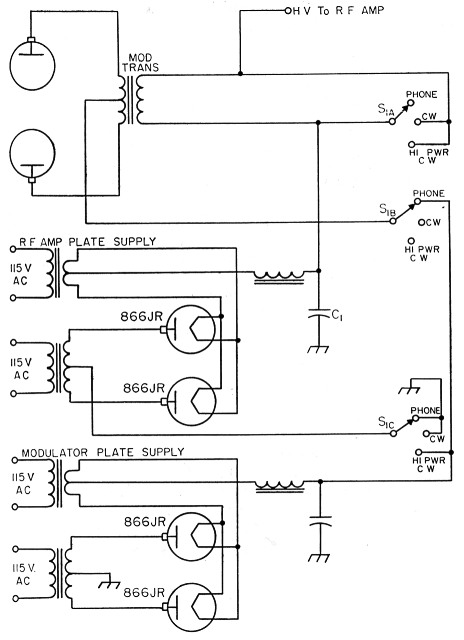
Fig. 1. Circuit diagram of the 600-1200-volt power supply. C1 should be rated at 1500 volts or more. S1 is a 3 pole 3 position ceramic rotary switch. Power transformer ratings are discussed in the text.
While building the "Final Rig" (that's the one that you think will be the last rig you'll ever build since it's going to have everything in it), I came up with the following gimmick which may be of interest to some rig builders.
Originally I planned to put a pair of 807s or equivalent tubes in the final, and so provided a 600-volt 250-ma. power supply for them. I also planned to use a pair of the same tubes as modulators, and provided a separate 600-volt 250-mA power supply for them. After both power supplies were installed on the chassis and working, I considered the fact that half of my available d.c. power was unused on c.w. A little thought evolved the circuit shown in Fig. 1.
Basically, the control is a 3 pole 3 position switch. In the phone position it runs the r.f. section from one 600 volt supply, and the modulator from the other. In the c.w. position it removes plate power from the modulators and shorts out the secondary of the modulation transformer. In the third position, called hi-power c.w., it places the two 600 volt supplies in series, giving 1200 volt at 250 mA for the final r.f. section. Ordinary 807s won't take that sort of power so I used a pair of 4-65As. These tubes draw practically the same plate current over a wide range of plate voltages - ratings being 150 mA each through the 600-1500 volt range. Screen voltage comes from the 250 volt supply used for the exciter and speech-amplifier sections.
Howard J. Hanson, W7MRX/