Rtty regulator circuit
In the process of building an RTTY converter, I ran into trouble regulating the 60 mA for the printer coils. The problem was solved by using the circuit shown in Fig. 1.
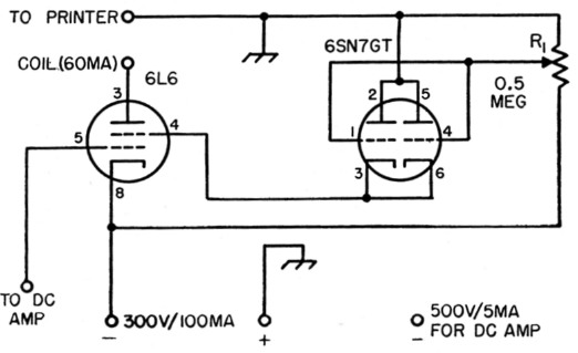
Fig. 1. Circuit diagram of the RTTY regulator circuit. R1 should have a linear taper.
In operation, the parallel 6SN7GT acts as a voltage regulator for the screen of the 6L6, holding the screen voltage to very close limits regardless of screen current. Under these conditions, the plate-current vs. plate-voltage curve of all beam power tubes comes into effect, thus holding the current in the plate circuit to the value selected by adjustment of the 0.5 megohm potentiometer. In practice, I found that the addition to the circuit of two more printing coils (1500 ohms each) plus 700 ohms of line dropped the printer current not more than 2 mA. The arrangement helped to straighten out the inductive lag in the build-up of the 60 mA It almost completely removes the mark bias previously present.
The circuit works directly into the printer coil without using the polar relay. I did this because the only polar relay on hand was bad and couldn't be quieted down. However, after using this for keying, I will never use another polar relay. No filtering whatever is necessary, and there is just that much less equipment to give trouble. The polar relay was never intended to be used for RTTY or short-haul work in the first place. Its intended use is on long lines where the excessive capacity results in a delay in the mark without a corresponding delay in space. The polar normally works into a circuit where the line furnishes 25 mA plus for mark and 25 mA minus for space. Thus any delay or other distortion on mark will be matched by a corresponding distortion on space, which can be compensated for in the adjustments in the relay. All this is unnecessary for RTTY or short-haul work.
Notice that the power supply used with Fig. 1 is connected with the plus side grounded (for safety reasons) and that it also furnishes voltage for the d.c. amplifier.
Eugene Austin, W0LZL.