A high-powered tetrode rig for 144 Mc
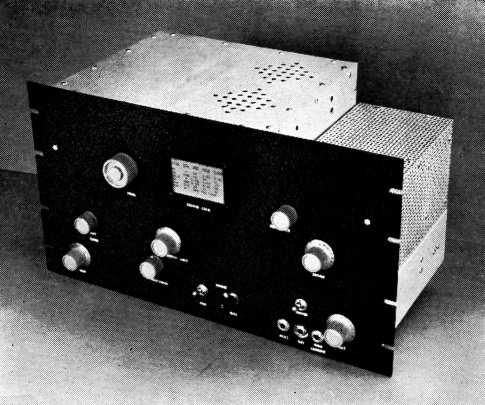
The high-powered 2-meter rig, with shielding enclosures in place. The small unit at the right houses the tripler and driver stages.
Improved performance for the 2-meter dx Enthusiast.
Check with anyone who is running high power xon 144 Mc., and you're likely to find that he's dissatisfied with the amount of power he has to run to his driver stage. Data sheets show that 4-125As, for instance, require only 6.6 watts driving power to the pair, but most 2-meter men employing these tubes end up with an 829B or 5894 in the driver stage, running at close to full rated power. Should it take 80 to 100 watts input to drive a tetrode final that runs 600 to 800 watts input on 144 Mc.?
This question bothered the writer for years, carrying through the design and use of the 4-125A rig that has been in the last three editions of the Handbook. That outfit did well at W1HDQ for several seasons, much of the time taking a full kilowatt input, on c.w. The original tubes were still in use when the rig was dismantled recently, so we have evidence that they were not too severely abused by such treatment. But that 9903 driver stage running at 80 watts input never seemed quite right. There should have been an easier way out of the high-power problem than that.
The driver stage showed good efficiency when checked with a dummy load. Where did all the power go? Some was being radiated, instead of coupled into the load. That could be helped by shielding. Some went into heating of the links, due to improper matching. Properly designed coupling circuits should correct this. There was heating loss in the final grid circuit; it ran hot, even though the inductance was ¼ inch copper strap. Better tank circuit design was an obvious move.
The old rig was rather critical in adjustment. Neutralizing was fussy, and there was a tendency for adjustments to drift appreciably when the final was operated at maximum power level. Antenna loading and modulation adjustments had to be watched closely. In short, the rig worked much like other high-powered 2-meter rigs we've seen. It put out a "big signal" but there was definitely considerable room for improvement.
With more than three years' experience with the first model to guide us, and following suggestions from several other high-power enthusiasts (W3LZD and W9MUD, among others) who had gone through a similar disillusionment with "low-drive" tetrodes, we set about the job of building a more modern version. It would be completely shielded. The driver portion would be a separate unit, so that either final or driver could be altered without upsetting the other. Where drive might be a problem, interstage coupling would be by means of coaxial line, with the coupling loops at each end provided with series capacitors to tune out their reactance. There would be provision for insertion of a standing-wave bridge in the links, so that the coupling circuits could be adjusted readily for minimum s.w.r. and maximum transfer of power.
The result is shown herewith. The same two 4-125As still burn brightly in the final stage, but they are driven adequately by an RCA 6524. This stage runs under 100 mA, plate and screen current, at 400 volts; about half the driver power used in the earlier model. The tripler stage that pushes the 6524 is an Amperex 6360 dual tetrode that loafs along at well below its full capabilities.
Neutralization is no longer critical, and only the variable screen-to-ground capacitor, C6 is needed. Maximum grid current, minimum plate current and maximum output coincide neatly at one setting of the plate tuning capacitor. Modulation characteristics of the amplifier show up well, and the plate and grid meters stand still when full modulation is applied. There is no gradual detuning when the amplifier is run for extended periods at maximum ratings. Reports on the signal are complimentary. If the reader draws the conclusion from the above statements that we are pleased with the way the new rig works, he's right.
The driver portion
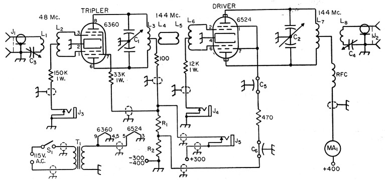
Fig. 1. Schematic diagram of the tripler and driver stages of the high-powered 2-meter transmitter.
| C1,C2 | 10.5 pF per section butterfly variable (Johnson 10LB15). |
| C3 | 25 pF screwdriver-adjustment variable (Hammarlund APC-25). |
| C4 | 25 pF miniature variable (Bud LC-1642). |
| C5,C6 | 500 pF feed-through by-pass (Centralab FT-500). |
| R1 | 11,000 ohms 2 watts (two 22,000-ohm 1-watt resistors in parallel). |
| R2 | 50,000 ohms 2 watts (two 100,000-ohm 1-watt resistors in parallel). |
| L1 | 2 turns insulated wire around center of L2. Twist leads to J1 and C3. |
| L2 | 13 turns No. 20, 5/8 inch diam., 7/8 inch long, center tapped (B & W Miniductor No. 3007). |
| L3 | 3 turns No. 14 enamel, ¾ inch diam., spaced 1/16 inch, center-tapped. |
| L4 | 2 turns No. 18 enamel, same as L3, inserted al center. |
| L5 | 2 turns No. 18 enamel, same as L6, inserted at center. |
| L6 | 4 turns No. 14 enamel, ½ inch diam., turns spaced wire diameter. |
| L7 | 2 turns No. 14 enamel, 1 inch diam., spaced ¼ inch. |
| L8 | 1 turn No. 14 enamel between turns of L7. |
| J1,J2 | Coaxial fitting, female (Amphenol 83-1R). |
| J3,J4,J5 | Closed-circuit jack. Insulate J5 from panel and chassis. |
| MA1 | External meter not shown in photo. 200 mA |
| S1 | Toggle switch. |
| T1 | Filament transformer, 6.3 V, 1 A (UTC: S-55). |
The tripler and driver stages both operate well inside their CCS ratings. Self-tuned grid circuits are used. This not only simplifies the layout, but in the driver it reduces the likelihood of self-oscillation. The 6524 grid circuit is resonant with the tube's input capacitance at around 130 Mc. There is little tendency to oscillation, therefore, and no neutralization is required.
An exciter delivering about 5 watts on 48 Mc. may be used, or if the builder already has a low-powered 2-meter rig it can be hooked up to the driver, omitting the tripler stage. The exciter currently in use at W1HDQ is a band-switching 6146 job(1) that was used with the former rig. If this seems like an excess of drive, let it be known that the 6146 is running at 10 to 15 watts input on 48 Mc. The tripler may also be driven by the 5763 doubler in the exciter, skipping the 6146 stage.
Tripler and driver are built on a standard 5 × 10 × 3 inch aluminum chassis, with the tripler at the back. Its plate circuit is tuned from the front panel by an extension shaft. To forestall the inevitable letters, omission of the screen by-pass on the tripler is intentional. This omission always bothers some readers, but if the stage works well without the by-pass, why put it in?
On the first check of the driver portion we found that the 6524 was being overdriven. This was corrected by squeezing the driver grid coil turns closer together, lowering the resonant frequency until the desired 2.5 to 3.5 ma. was obtained across the band. The farther it can be resonated below 144 Mc. the less likelihood there is of self-oscillation in the driver stage.
The 6524 is mounted horizontally, and holes are drilled in the chassis under the tube to allow for air circulation. Plate leads are made of thin phosphor bronze or copper, bent into a semicircle, connecting the butterfly capacitor and the heat-dissipating connectors. This allows the latter to be removed for changing tubes, without putting undue strain on the plate pins. The connectors have to be sawed or filed down on the insides to fit on the 6524 pins. The coupling link at the driver plate circuit is tuned, to provide efficient transfer of energy to the amplifier grids.
Small feed-through by-passes are used in the driver screen circuit. C5 is mounted in the aluminum plate that supports the 6524 seocket, and C6 is in the chassis surface.
Amplifier features
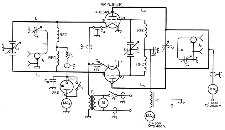
Fig. 2. Schematic diagram of the 4.125A amplifier for 144 Mc.
| C1 | 30 pF per section split-stator variable (Hammarlund HFD-30X). |
| C2 | Plate tuning capacitor made from Millen 15011 neutralizing unit; see text and photo. |
| C3 | 25 pF miniature variable (Bud LC-1642). |
| C4,C5 | 500 pF feed-through by-pass (Centralab FT-500). |
| C6 | Approx. 50 pF per-section split-stator variable. Make from Millen 19140 or Hammarlund MC-140; see text. |
| C7 | 25 pF variable (Johnson 25L15). |
| C8 | 0.25 µF tubular. |
| R1 | 5000 ohms, 10 watts. |
| L1,L2 | ¼ inch copper tubing, 12 inches long, spaced 1½ inches center to center. Bend around 1½ inch radius, 1 inch from grid end. |
| L3 | Loop made from 5 inches No. 14 enamel. Portion coupled to line is 1 inch long each side, about 3/8 inch from line. |
| L4,L5 | ½ inch copper tubing 12 inches long, spaced 1½ inches center to center. Bend around 2 inch radius to make line 4 inches high. Attach C2 4½ inches from plate end. |
| L6 | Loop made from 7 inches No. 14 enamel. Sides spaced 1¼ inches. |
| L7 | 5 H (min.) 100 mA rating filter choke. |
| J1,J2 | Coaxial fitting, female (Amphenol 83-1R). |
| MA1,MA2,MA3 | External meters, not shown; 100, 200 and 500 mA. |
| M | Motor-blower assembly, 17 c.f.m. (Ripley Inc., Middletown, Conn., Type 8433). |
| RFC | V.h.f. solenoid choke (Ohmite Z-144). Four required. |
| S1 | Toggle switch. |
| S2 | Rotary jack-type switch (Mallory 720). |
| T1 | Filament transformer, 5-volt 13-amp. (Chicago FO-513). |
Difficulties with the former 4-125A grid circuit indicated that experimentation was in order at that point in the new unit. The input capacitance of 10.8 pF per tube makes it impossible to use a conventional tuned grid circuit at 144 Mc., so a half-wave line was tried in the amplifier. This and the series-tuned coupling link, plus shielded construction, resulted in markedly better driver efficiency than we had heretofore obtained. The grid line, L1L2, was originally made of No. 12 wire. This ran hot, so ¼ inch copper tubing was substituted, with improved results.
Maintaining the 4-125A screens and filament leads at ground potential for r.f. is important in achieving stability. To this end, the tube sockets are mounted above the chassis, rather than below. They are elevated only enough to allow the socket contacts to clear the chassis, and are mounted corner to corner, with the inner corners almost touching. The grid line is brought up through %-inch chassis holes and soldered directly to the grid contacts. This determines the line spacing, about 1½ inches center to center.
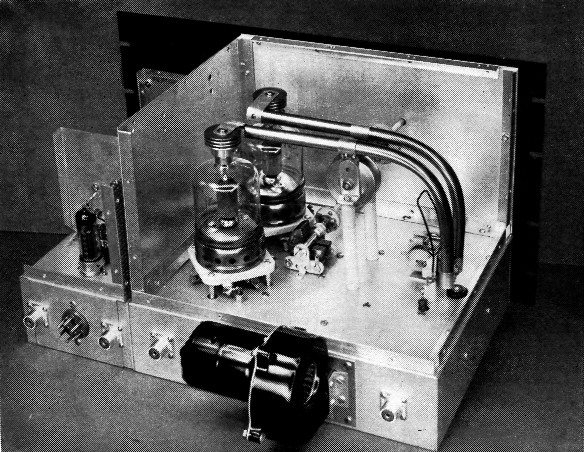
Rear view of the 4-1254 final stage. The split-stator capacitor near the middle of the picture is the screen neutralizing adjustment. The plate line is tuned with a capacitor made from parts of, a neutralizing unit, mounted on ceramic stand-offs.
The inner filament terminals on each socket are grounded to the chassis. The others connect to feed-through by-passes with the shortest possible leads. These are joined under the chassis with a shielded wire and tied to the filament transformer. The r.f. chokes in the screen leads are under the chassis, their wire leads coming up through Millen type 32150 feed-through bushings inserted in chassis boles under the screen terminals. The two screen terminals on each socket are strapped together with a 4 inch wide strip of flashing copper. The screen neutralizing capacitor is mounted as close to the sockets as possible and still leave room for the shaft coupling on its rotor. Leads to its stators are about one half inch long.
More compact and symmetrical design is possible if a modified single-section capacitor is used for C6. It should be the type having supports at both ends of the rotor shaft. The Millen 19140 and Hammarlund MC140 are suitable units for the purpose. The stator bars are sawed at each side of the center stator plate. The front rotor plate is removed, making a split-stator variable with 4 plates on each stator and 8 on the rotor. This procedure may not be applicable to all 140 pF capacitors. hut. any method that results In a balanced unit having about 50 pF per section should do.
Construction of the final plate circuit should be clear from the photographs. Tuning is done with parts of a disk-type neutralizing capacitor (Millen 15011) mounted on ceramic stand-offs 3M inches high. These are made of one 1-inch and one 2%2-inch stand-off each, fastened together with a threaded insert. Connection to the lines is made with copper or silver strap, 4M inches from the plate end. Silver plating of all tank-circuit parts is a worth-while investment. though it should not be considered a necessity. A shaft coupling designed for high-voltage service is attached to the threaded shaft of the movable plate, and this is rotated with a shaft of insulating material brought out to the front panel.
A word about the extension shafts is in order at this point. If they are of metal they may have a serious detuning effect in some circuits, even though they are connected through insulating couplings. Originally we used h-inch lucite rod, which looked very nice, but it wilted in a hurry when the final enclosure was buttoned up and the rig operated at high power. Bakelite rod is fine, but since the insulating qualities are of no importance, ¼ inch wooden doweling will do the job just as well. Suitable doweling can he bought for about 5 cents per 3-foot length at most hardware stores.
The final cbaaais is aluminum. 10 × 12 × 3 inches, matching up with the driver chassis to fit a standard 10½ inch rack panel. Complete enclosure is a must for TVI prevention, and it pays dividends in improved stability by providing effective isolation of circuits that tend to give trouble in open layouts. TVI drove us to the use of enclosed rigs, but the improvement in performance that has resulted from the step makes the old TVI threat take on the aspect of a blessing in disguise, even though it makes some extra work and brings on the need for forced-air cooling.
The enclosures were made by mounting M-inch aluminum angle stock around the edges of the chassis of both units and cutting the sides and covers to fit. It was not intended to cool the driver unit originally, so the enclosure was made of perforated aluminum. The blower for the final provided plenty of air, however, so three holes were made in the walls of the two chassis to allow some of the air flow to go through the driver enclosure as well. The chassis are bolted together where the vent holes are drilled. The main flow is up through the amplifier chassis. around the 4-125As, and out through the M-inch holes drilled in the top cover above the tubes. Holes in the amplifier chassis are drilled to line up with the ventilating holes in the 4-125A sockets. All other holes and cracks are sealed with household cement to confine the air to the desired paths, and bottom covers are fitted tightly to both units.
The somewhat random appearance of the front panel is the result of the development of the unit in experimental form. A slight rearrangement of some of the noncritical components could be made to achieve a symmetrical panel layout readily enough.
Operation
The two units have their own filament transformers. Plate supply requirements are 300 V at 50 mA for the tripler, 400 V at 100 mA for the driver, 300 to 400 V at 75 mA for the final screens and 1000 to 2500 V at 400 mA for the final plates.
The driver plates and final screens may be run from the same supply, but more flexibility is possible if they are supplied separately. A variable-voltage supply for the final screens is a fine way to control the power level, a desirable feature in a v.h.f. station. At W1HDQ the high-voltage supply provides a choice of 1100 or 2500 V for the 4-125A plates. This is done by switching in the 220 or 110 volt primary on the plate transformer, resulting in inputs of 300 or 800 W at the flip of a switch. All work except DX schedules on c.w. is normally done at the lower level. The screen supply is variable from zero to 400 V by means of a small Variac in the primary circuit of its power transformer.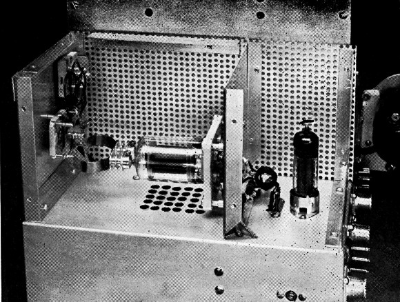
Side view of the tripler and driver stages. Coil adjacent to the 6360 tripler tube is the grid coil for the 6524 driver. Plate leads for the driver tube are flexible copper straps, to permit removal of the tube from its socket. Screwdriver adjustment at the lower right is the reactance tuning capacitor for the tripler input link.
In putting the rig on the air the stages were fired up separately, beginning with the tripler. A jack (J3) is provided on the front panel for measuring the 6360 grid current. About 1 ma. through the 150,000-ohm grid resistor is plenty of drive. The series capacitor, C3, in the link can be used as a drive adjustment, if more than necessary is available.
Next plug the grid meter into the 6524 grid current jack, J4, and tune the 6360 plate circuit for maximum grid current. It need be no more than 3 to 4 mA, with no plate voltage on the driver. If it is higher than this value increase the inductance of the grid coil, L6, by squeezing its turns closer together.
Now apply plate and screen voltage to the 6524, and check for signs of self-oscillation. There should be none across the band, though if the plate circuit is tuned down to the same frequency as that at which the grid coil resonates with the tube capacitance, the stage may take off on its own. As long as it is stable across the intended tuning range there should be no operating difficulty resulting from a tendency to oscillate lower in frequency, and no neutralization should be needed.
Connect a coaxial line between the driver output and the final grid input, preferably with a standing-wave bridge connected to indicate the standing-wave ratio on this line. A Micro-Match or similar power-indicating bridge is ideal for this application, as it may be left connected in the circuit while adjustments are made with full driver power. Tune the driver plate circuit and its series-tuned link for maximum forward power on the Micro-Match indicator, or for maximum grid current in the final amplifier. Adjust the final grid tuning, C1, for maximum grid current, and the series capacitor, C3, in the link for minimum reflected power on the s.w.r. bridge. Adjust the coupling loop position for maximum transfer of power, setting it at the least coupling that will achieve this end. Recheck all adjustments carefully.
Adjust the screen neutralizing capacitor for maximum final grid current, with the plate voltage off. Now we're ready to fire up the final.
Rule 1: Never operate a tetrode final stage having a fixed screen supply without load! The screen dissipation goes sky high when the plate load is removed, or is made too light, and the tube can fail in short order. It is important to meter the screen current at all times. With 4-125As you can tell if you're endangering the plates by their color, but the screen-current meter is all that can save you from tube damage to that element.
We know of no inexpensive dummy load that is suitable for testing a high-powered v.h.f. rig. Lamps are out; they don't come even close to simulating the 50- or 75-ohm load you must have to adjust a coax-output rig of this power level. The best thing we know of is an antenna, and that's what was used in setting up the initial adjustments on this job - a gamma-matched dipole, fed with coax. It was strung up in the basement laboratory at Headquarters, and its series capacitor adjusted for a standing-wave ratio of close to 1:1. The Micro-Match saw service in this operation, but it was none too happy with the 500 watts or so of r.f. that the 4-125As are capable of delivering. Better make such adjustments at something less than full power, and don't take the "forward power" indication too literally. Watch out for any sign of heating in the bridge unit, or you may have to buy a new one soon.
The position of the coupling loop, L6, should be adjusted for maximum transfer of energy to the antenna, keeping the coupling as loose as possible. The series capacitor, C7, can be used as a loading adjustment thereafter. If the screen voltage is continuously variable it will ba found that there is a range around 325 to 350 volts where the efficiency of the final stage seems to peak. Using the variable-voltage supplies in the ARRL Lab set-up, here are some typical conditions of operation:
| Stage | Up | Ip | Ug2 | Ig2 | Ig1 |
|---|---|---|---|---|---|
| Tripler | 300 V | 35 mA | - | - | 1.5 mA |
| Driver | 400 V | 92 mA | - | 8 mA | 3-4 mA |
| Final | 1000 V | 300 mA | 400 V | 60 mA | 22 mA |
| Final | 2000 V | 350 mA | 350 V | 45 mA | 20 mA |
| Final | 2500 V | 400 mA | 320 V | 40 mA | 18 mA |
The first and third conditions given for the final stage represent extremes, both exceeding the tubes' ratings in some way, so they are not recommended. At low plate voltages the screen has to be run above recommended ratings to make the tubes draw their full rated plate current and operate efficiently. At high plate voltages the screen dissipation drops markedly. The use of 4-125As at a full kilowatt input is a considerable stretching of the manufacturer's maximum ratings, and is done at the user's risk. It should not be attempted except in c.w. work, where the periods of maximum dissipation are short. To operate safely, the maximum plate voltage for voice work at 144 Mc. should probably not go over 2000. At this level the tubes will handle 600 watts input very easily on voice, and 750 watts on c.w. is certainly no strain.
Modulation and keying
Use of c.w. is increasing steadily on 144 Mc. It is a must for weak-signal DX work, and some of the gang prefer c.w. to voice for routine rag-chewing purposes. We strongly recommend that every 2-meter rig include provision for keying, even though the builder is not a c.w. man at heart.
Keying in this rig is done in the screen circuit of the driver stage, and in the screen and plate circuits of the tripler. Cathode keying of the driver was attempted, but it brought on instability troubles, so was abandoned. The screen method makes the key hot, so an insulated key or a keying relay must be used in the interest of safety. The keying jack must, of course, be insulated from the panel.
Fixed bias for the final amplifier is provided by the VR-tube method. When the tube ignites at the application of drive, the capacitor C8 charges. Removing excitation stops the How through the VR tube and leaves the negative charge in the capacitor applied to the amplifier grids. The effectiveness of this system depends on the leakage characteristics of the capacitor, so it may be necessary to try several types to find one that will hold the charge sufficiently. The value is not important, and oddly enough the best one we found was an inexpensive paper tubular type of uncertain vintage.
Modulation is applied to the plates only. A choke of about 10 H is connected in the screen lead, or the modulation can be supplied through a screen winding on the modulation transformer. In either case the by-pass value in the screen circuit should be low enough to avoid affecting the higher audio frequencies. Occasionally audio resonance in the screen choke may cause a singing effect on the modulation. If this develops, the choke may be shunted with a resistor. Use the highest value that will stop the singing. Too low a resistance will impair the effectiveness of the choke in its modulation role.
In neutralizing the 4-125As it may be found that what appears to be the best setting of the screen capacitor will result in a very large drop in grid current when plate voltage is applied. The setting may be altered slightly, raising the full-load grid current, without adversely affecting the stability of the amplifier. For example, the grid current with no plate voltage may be 25 ma. or so. When the plate voltage is applied and the amplifier loaded up, the grid current may drop as low as 10 to 12 ma. The screen capacitor may be reset until the full-load grid current is about 18 ma., without there being any tendency toward oscillation. The final check for neutralization is twofold. There should, of course, be no oscillation when drive is removed; and maximum grid current, minimum plate current and maximum output should all show at one setting of the plate tuning capacitor. The latter condition may be observed only when the amplifier is operated without fixed bias.
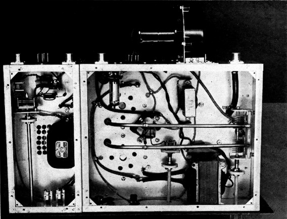
Under-chassis view of the 2-meter transmitter. Tripler grid and plate circuits are at the upper left. Only two of the three jacks on the front panel show in the lower left. The halfwave line used in the 4-125A grid circuit is the main item of interest in the amplifier section. Both units are fitted with bottom covers, to provide shielding and confine the flow of cooling air to the desired areas.
It may be desirable, especially if c.w. is to be used regularly, to make provision for changing the grid-leak resistance. At W1HDQ a 5000-ohm 25-watt potentiometer is connected in the grid return lead. This is readjusted to permit running the same value of grid current, whether or not the VR-tube bias arrangement is in use.
Three different makes of 4-125As have been used in the new final amplifier, Eimac, GIB; and Amperex. The Amperex tubes, also known as 6155s, are quite different in design from the other two makes, but except for a slight difference in final plate tuning they seemed to work identically with the others. This uniformity of operation with different tubes is of interest, because the earlier model required markedly different adjustments with the same three sets of tubes to achieve anything approaching stable operation.
The new rig has been in use at W1HDQ for several months, during which we've had ample time to iron out bugs in its design. Its principal features have also been incorporated in a similar set-up built by W1VNH, Agawam, Mass., who reports it as being the most stable and satisfactory tetrode rig he has had on 144 Mc.
Notes
- Tilton, "A high-powered driver-amplifier for 144 Mc.," QST, July, 1952, p. 11.
Also, The Radio Amateur's Handbook, 30th, 31st and 32nd editions.
Edward P. Tilton, W1HDQ.