A super-selective converter
Improving the performance of a small receiver.
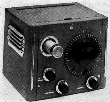
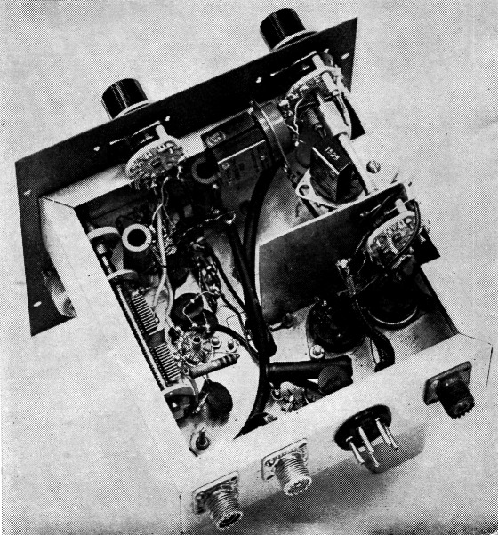
This "super-selective converter" is a complete receiver front end plus a two-stage 1525 kc. crystal lattice filter. It is intended to work ahead of any receiver capable of tuning to 1525 kc. The oscillator coil is plug-in, at the upper left.
Here is an interesting article about a gadget that will improve small-receiver performance without too great a cash outlay. It is a tunable converter followed by a 1525 kc. crystal lattice filter, which will add tuning ease and high selectivity to any receiver capable of tuning to 1525 kc.
How could I improve the performance of my economy receiver? Adding a Q5-er or a crystal filter would provide the necessary selectivity, but the front-end stability wasn't enough to hold high-frequency signals with the present selectivity. And, of course, a smooth vernier bandspread dial would add greatly to operating pleasure.
It looked like a new front end and a new back end were needed. Since this seemed like going a little too far in trying to save our original investment, an attempt was made to build selectivity into a new front end. The results have been very satisfying.
The solution was to use a 1525 kc. cascaded half-lattice crystal filter in the output of a new front end. The result is a converter with built-in steep skirt selectivity closely approaching the best commercial receivers and featuring good stability, adequate sensitivity and calibrated bandspread. Although no actual tests were made, it seems likely that this arrangement would have a minimum amount of overloading and cross-modulation difficulties, because the selectivity is introduced at the earliest possible stage.
Some of the mobile hams may want to go a step further in working out a 1500 kc. filter in a mobile converter or as an insertion unit between a converter and a regular b.c. set in the car.
The Circuit
The filter circuit is similar to one of those described by Burns,(1) except that it was necessary to ground the load resistor between sections a little differently, in order to obtain balance with the layout used. This can be seen in Fig. 1.
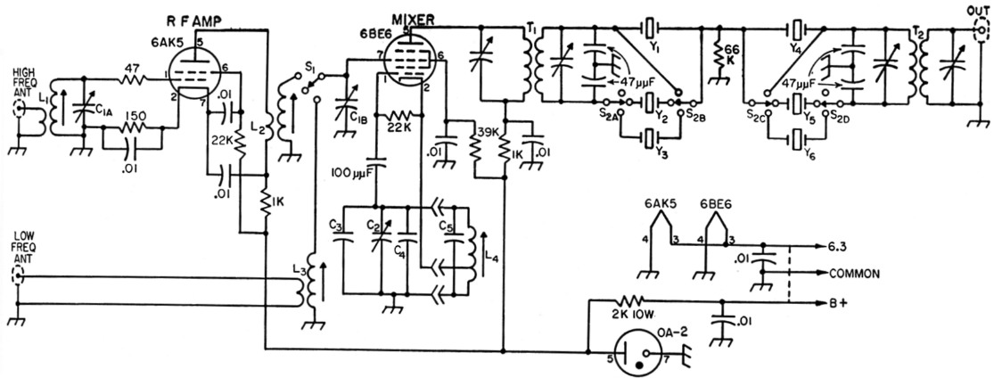
Fig. 1. Schematic diagram of the super-selective converter.
| C1 | Split-stator variable, 100-pF-per-section (Hammarlund MCD-100-S). |
| C2 | 35 pF variable (Hammarlund MC-35-SX). |
| C3 | 50 pF temperature-compensating, N750 type (Centralab TCN). |
| C4 | 39 pF silver mica. |
| L1 | 12 turns No. 18 enam. close-wound on National XR-50 form. Common ground tap at 2 turns. |
| L2 | 10 turns No. 18 enam. close-wound on National XR-50 form. Primary winding, 4 turns No. 18 enam. adjacent to ground end. |
| L3 | 44 turns No. 26 enam. close-wound on National XR-50 form. Common ground tap at 4 turns. |
| L4 | 3.5 Mc.: 26 turns No. 26 enam., close-wound. Cathode tap at 5 turns. C5 10 pF silver mica. 7 Mc.: 20 turns No. 26 enam., close-wound. Tap at 4 turns. C5, 15 pF silver mica. 14 Mc.: 6 turns No. 18 enam., spaced to occupy 3/8 inch. Tap at 2 turns. C5, 20 pF silver mica. 28 Mc.: 3 turns No. 18 enam., spaced to occupy 3/8 inch. Tap at 1 turn. C5, 25 pF silver mica. Each L4 wound on Millen 74001 plug-in shielded form, ½ inch diam. |
| S1 | Single-pole 3-position rotary. |
| S2 | Made from two 2-pole 3-position rotary switches (Centralab PA-2011 with one section removed and Centralab PA-2003). See photograph. |
| T1,T2 | 1500 kc. i.f. transformer (Merit BC-315). |
| Y1-Y6 | See text. |
In working with the 1525 kc. crystals, they were found to function the same as the 460-kc. crystals described by Morrison.(2) As he mentioned, the basic requirement is to use the proper LC ratio to suit the crystals being used. The necessity for switching out both sides of the unused crystal, as well as the effect of a small trimming capacity across the high frequency crystal, were also verified.
The 6AK5 r.f. stage operates only on 14 Mc. and above, to simplify bandswitching and reduce the possibility of overloading. Separate antenna connections are provided for the low (3.5 and 7 Mc.) and high ranges (14 and 30 Mc.). No r.f. gain control is provided, since the r.f. stage can be detuned slightly in the few cases where it might be necessary. The 47-ohm resistor in the grid is a parasitic suppressor and might be eliminated with a little more work.
The 6BE6 uses a high-C oscillator circuit with a double-bearing 35-pF bandspread condenser that has wide-spaced plates. The values of inductance and capacitance in the oscillator portion of the circuit were selected so that on all bands (except 28 Mc.) the frequency will be approximately equal to the dial reading plus the low-frequency edge of the band in kc. For example, on the 7-Mc. band, dial readings from 0 to 500 on the National PWO dial will be from 7000 kc. to 7500 kc. so that 250 on the dial represAnts 7250 kc., etc. On 10 meters, 0 to 400 on the dial covers 28 to 30 Mc.
A OA-2 miniature voltage regulator tube is included to maintain a constant 150 volts on the 6BE6 and 6AK5.
It was found necessary to provide good isolation or shielding between the two half-lattice sections. By-passing of the power leads returning to the receiver prevented leakage of the signal around the filter and improved performance.
The Merit type BC-315 i.f. transformers provided a satisfactory match for the crystals without modification of the windings. The 47ssf. silvered midget micas were soldered directly to the terminals inside the respective i.f. shield cans. The output i.f. transformer was modified to leave the output coil untuned. A Merit BC-314 was tried but the center-tapped coil was not balanced well enough to eliminate the need for the condensers, so the BC-315 without center tap was used.
Crystals
The crystals used were 1525-kc. FT-243 type available on the surplus market. Surplus 1632.5kc. crystals were also found to work satisfactorily. Two of the six crystals needed were shifted 2 kc. higher by grinding with a few figure-eight strokes on a piece of plate glass, using fine water-mixed valve grinding compound as an abrasive. Two others were shifted 8 kc. higher in the same manner, while the remaining two were used without change. Although this part of the job seemed easy, a couple of practice crystals may be needed unless previous experience has been acquired. Checking the crystal frequency as grinding progresses will be discussed later.
Construction
Although the use of the National PWO dial has turned out to be a most satisfying feature, its size increased the difficulty of obtaining an optimum chassis layout.
The usual precautions in rigidity of wiring and component mountings must be observed if good stability is to be obtained.
The complete converter is mounted in an ICA type 3860 cabinet using a 7 × 7 × 2 inch aluminum chassis which is mounted 14 inches up from the bottom of the panel. A cut-off chassis bracket was used to mount the oscillator tuning condenser and to steady the chassis. The socket for the oscillator plug-in coil was mounted on a "below the panel" socket shell. The crystals are plugged into octal sockets with no extra shielding except that provided by a handmade aluminum bracket, as can be seen in one of the photographs. Since there are only two terminals on the National XR50 coil forms, L1 was wound onto the coil form and held in place by soldering leads into the circuit after the coil is mounted. The terminals for the taps on L1 and L3 were formed by making a small loop in the wire at the tap point and continuing the winding. In coil L3, the turns after the ground tap were separated from the main part of the coil by winding the remaining turns on the base portion of the coil form just below the terminal. This was necessary in order to maintain enough selectivity for image rejection.
In the oscillator circuit the condenser C6 was mounted inside the coil shield of each oscillator coil.
Alignment
The method of alignment depends upon the test equipment available, and the following description applies to a method that can be used with a minimum of available equipment.
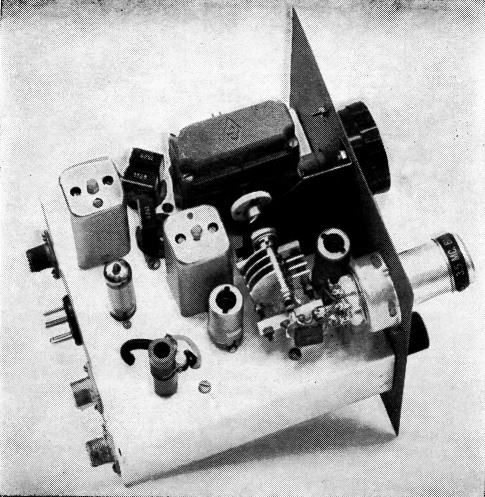
Top view of the super-selective converter. The tuning capacitor, mounted on the partition, has been changed since the photograph was taken. The slug-tuned coil in the lower left is the high-frequency coil, L1. The 6AK5 r.f. stage is to the right of L1 - the 6BE6 mixer is close to the panel.
After checking the wiring, the power is connected and the converter allowed to warm up. If the regulator tube is not glowing, the 2000 ohm dropping resistor should be reduced until glowing indicates that the regulator is operating.
Before working on the crystals or crystal filter, it is desirable to align and check the converter on at least one band with the filter out. The selectivity switch, S2, is turned to the "filter out" position, the bandswitch, Si, is set to the low range, and the 3.5 Mc. oscillator coil is plugged in. The crystals need not be plugged in yet. The output of the converter is connected to the antenna terminals of the receiver to be used, and an antenna is connected to the low-frequency antenna input of the converter.
Set the receiver by its own calibration as close as possible to 1525 kc. (or the i.f. frequency to be used).
Peak up the noise or signals on the r.f. tuning and then peak the i.f. transformers, T1 and T2. Some systematic juggling of the i.f. transformers and the r.f. tuning may be required to get them peaked simultaneously. Of course, a grid-dip meter to check the r.f. tuning, and a signal generator to aid in aligning the i.f. transformers, would be helpful. The slug in the mixer coil can then be adjusted so that r.f. peaking occurs near the high capacitance end for the 3.5 Mc. band.
Now the antenna is disconnected and a signal of known frequency in the 3.5 Mc. band (from a crystal oscillator or VFO) is connected to the converter input through a small capacitance of 10 pF or less. Set the dial to correspond to the signal frequency. For example, if the signal is 3700 kc., set the dial at 3700 minus 3500, or 200. Adjust the slug in the oscillator coil until the signal is heard. Change the frequency of the VFO or crystal oscillator and tune in the signal with the main dial. The new dial setting should agree closely with the new signal frequency. The calibration across the band should be within 15 kc. on the 3.5 Mc. band, 5 kc. on the 7- or 14 Mc. band and about 50 kc. on the 28 Mc. band. Higher values of C2 will reduce the band covered across the dial, and vice versa. The calibration can be set to favor the part of the band being used at the time. This is done by adjusting the oscillator coil slug so the dial reading is exact for a known frequency signal in the center of that portion of the band being used.
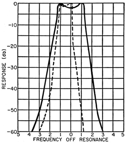
Fig. 2. Response curve of the converter and S-20-R receiver. The solid line is for the phone filter, the dashed for c.w.
After it is verified that one dial division equals approximately 1 kc., the work on the crystals can begin. Switch to the phone setting and insert one of the crystals in the Y1 socket. Short across the Y4 socket and again tune in the VFO or crystal oscillator signal. If an S-meter is not available on the receiver, it will be necessary to connect a vacuum-tube voltmeter or a 20,000 ohms/volt d.c. voltmeter (2.5-volt scale) across the diode load resistor, as described by Howard Morrison. The a.v.c. should be turned off and the r.f. gain of the receiver adjusted to give a reasonable reading on the meter.
A sharp peak in the tuning will indicate when the signal is being converted to the series resonant frequency of the crystal. The receiver and i.f. transformers should be trimmed to align on this peak.
Each of the crystals to be used can now be tried in socket Yl. They should all peak at the same dial setting and within a couple of dB of the same meter reading. All of the several crystals tried at W9YQL were matched well enough.
At this point the converter can be used to check the crystal grinding operation. After each trial grind, the crystal is cleaned, assembled and plugged into position Y1. With the input signal held to a constant frequency, the dial reading for two of the crystals (Y2, Y5) should be shifted 2 divisions (2 kc.) and .8 of a division for two others (Y3, Y6).
Plug in a 1527 kc. crystal in position Y2 and a 1525 kc. crystal in position Y1, leaving the short across position Y4. Set the dial between the two crystal peaks and trim up the i.f. transformers. Tuning across the signal will show the effect of one section of the filter. Adding a small capacitance across the 1527 crystal will produce steeper aides on the selectivity curve but too much capacitance will bring in objectionable side lobes. The capacitance used here was obtained by twisting short lengths of insulated wire. It was adjusted so that the side lobes were at least 35 dB down. When the characteristics of this section are satisfactory, the crystals are removed and the other set of 1525 and 1527 kc. crystals is plugged into positions Y4 and Y5. The procedure is repeated for the second section of the filter with a short across position Y1.
Bottom view of the converter. The selectivity switch, at the right, is made from two ganged sections, to provide isolation between the sections of the filter.
Next, all the crystals are plugged in and the characteristic phone and c.w. curves as shown in Fig. 2 should result. Less crystal-frequency separation can be used for c.w. if a narrower bandwidth is desired.
In using other i.f. transformers, it should be noted that an excessive dip in the center of the curve indicates too low an inductance in the coil. A rounded or peaked curve indicates too high an inductance. Reference should be made to the two articles by Morrison, which have been very helpful here at W9YQL in building and aligning this converter.
The remaining oscillator coils should be adjusted and the bandapread checked as described above. When the high-frequency range is checked, the slugs in the r.f. coil and the high-frequency mixer coil should be peaked together so the r.f. tuning is near the high-capacitance end for the 14 Mc. band.
In general, the performance of the converter has been very satisfactory. In some cases, as in an extremely quiet location or where a short receiving antenna is used, it might be advantageous to include the r.f. stage in the 7 and 3.5 Mc. ranges, but the need for it hasn't been felt here yet. The main objective of this article was to report that 1500 kc. crystal lattice filters are both practical and extremely useful.
Notes
- Burns, "Sideband filter using crystals," QST, Nov., 1954.
- Morrison, "Phone selectivity for the BC-312," QST, Feb., 1954.
"Cascaded half-lattice filters for phone and c.w.," QST, May, 1954.
John L. Tregay, W9YQL.